Display Shading
Updated August 25, 2020
This article applies to:
- RoadEng Civil
- RoadEng Forestry
- Softree Optimal
Display shading is a new feature in RoadEng Version 9. It allows the user to hatch portions of their road design in the plan view.
It has several functions including:
- the display of areas in cut/fill,
- displaying surfaces (SG, Srf 1, Srf 2, etc.),
- displaying areas between code pairs, and
- graphically illustrate attribute values in the plan view.
The feature can be accessed from the Plan Window Display Options dialogue box.
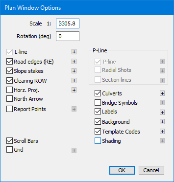
To toggle the feature on/off, simply check the Shading option. To configure the shading settings, press the “+” symbol next to Shading to open the Plan Shading Options dialogue box as shown in the figure below.

Figure 1 - Accessing the Plan Shading Options dialogue box through the Plan Window Display Options dialogue box.
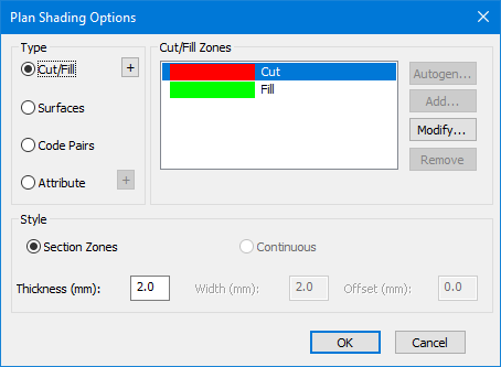
In the Plan Shading Options dialogue box (Figure 2) the user can select what type of shading they would like, configure what options are displayed, and select the desired color and hatch pattern.

Figure 2 - The Plan Shading Option dialogue box were shading options can be configured to display desired results.
By using this feature, design and construction considerations can be communicated more efficiently in the plan view. This can reduce the designer's time required to add labels, reduce clutter, draw attention to important details, and reduce the attention the designer/reviewer/builder must pay to other views.
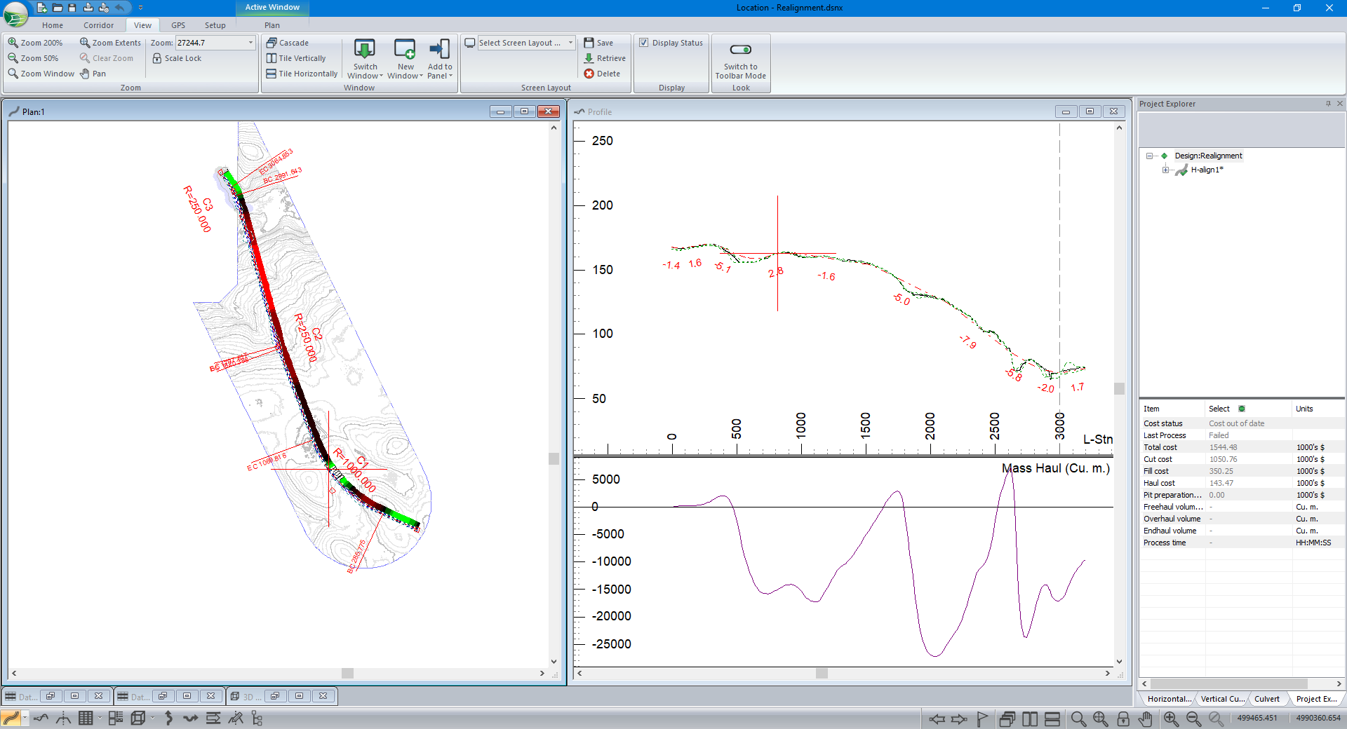
The option to display areas in cut and fill (Figure 3) is useful for both streamlining the design process and improving communication to builders. By using this feature in the preliminary stages of design in hilly terrain the user can quickly set the elevation of control points and adjust their horizontal alignment to achieve a desired balance of cut and fill without having to look between several design views. From a construction standpoint, the feature can be beneficial to show builders where they should transition between cut and fill.
Figure 3. An example design that illustrates areas in cut and fill using the cut and fill shading feature.
The remaining features can be used to:
- Delineate areas where different materials are required, for example, subgrade vs subbase (Figure 4)
- Draw attention to important areas using point codes (Figure 5),
- Delineate areas of interest based on attribute values and/or customize how attributes are displayed by their value (Figure 6).


