Creating a Skewed Section Example
Updated November 21, 2025
This article applies to:
- RoadEng Civil
- RoadEng Forestry
In this example we will demonstrate how to create a skewed cross section view along a road corridor. To do this we will export design surfaces from Location to a Terrain (*.ter) file and then ‘cut’ a section through them.
Download the example file package HERE
Download the PDF version of this tutorial HERE
Exporting designed surfaces
1. Start the Location module .
2. Choose menu File | Open, select file Alignment 1.dsn included with this example (see above). Press Open.

Figure 1 – Alignment 1.dsn
The template in this example has a variety of surfaces.For this example we will include the following surfaces:
- Stripping
- UC – undercut
- SG – subgrade
- GCB – fill layer
Notice the design has reporting points at 5m spacing. This spacing will improve the accuracy of the generated surfaces and therefore the accuracy of the section.
3. Choose menu File| Save As. Select Save as type Terrain File (*.ter) and enter Stripped.ter as the file save name. Press Save.

Figure 2 – Location design saving to a Terrain File.
4. When the Export to Terrain dialog appears, set the parameters as shown in figure below. In particular, set the Surface to Stripped Surface.

Figure 3 – Export to Terrain options with Stripped Surface selected
When the export completes we will have saved the Stripped surface in a terrain file.
5. Repeat steps 3 and 4 above to save surfaces:
- UC.ter (surface SubCut)
- SG.ter (surface Subgrade material)
- GCB.ter (surface GCB)
Creating the Skewed Cross Section
6. Choose menu Module | To Terrain to open the Terrain module .
7. Choose menu File | Open, select file Topo.ter (included with this example). This is the original ground surface used in the Alignment 1.dsn Location design. Press Open.

Figure 4 – Topo.ter viewed in the Terrain module.
We will now create a cross section. This is done in Terrain, by first creating a draped feature, then using this feature to create a profile.
8. Choose menu Edit | New Feature; this will open the Feature properties dialog box (figure below).
9. Set the feature name to “Section” (for organizational purposes) and set the properties as in the figure below (this will create a draped feature – it will follow the foreground terrain surface):

Figure 5 – Feature Properties Dialog; properties set for a draped feature.
At this point we have the option of drawing the new feature with the Mouse or typing in coordinates with the Keyboard (we won’t assume that you have a Digitizer connected). If you are familiar with drawing with the mouse in the Terrain module (similar to alignment editing in the Location module) then you can skip the following two steps and instead press the mouse button. Draw a two point feature similar to the one in Figure 7.
10. Click on the Keyboard button to open the Feature coordinates dialog box; respond OK to the Draped feature outside model warning.
11. Enter the coordinates as shown in the figure below:
- X: -75250, Y: 971300
- Press the Add button
- X: -75100, Y: 971450
- Press OK when complete

Figure 6 – Feature Coordinates Dialog

Figure 7 – Plan Window after adding the Section Feature
12. Choose menu Window | New Window | Graphics | Profile to create a new Profile window
NOTE: When you create a new Profile window the current feature (in this case the one created above) is used to define the view; this feature is called the fence feature. You can change the fence feature position or shape and the Profile will update.
13. Click on the Zoom Extents button (in the Zoom too bar) and respond OK to turn off autoscale.

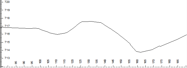
Figure 8 – Profile Window showing the draped Section feature (with vertical exaggeration).
The figure above shows a profile of the original ground surface Topo.ter. We will now include the additional template surfaces as background Terrains.
14.Right click in the Profile window and choose menu Active Window (Profile) Options.
15. Adjust the Horizontal and Vertical Scales to 500 and 100 respectively (as in the figure below). This will provide vertical exaggeration (if you have a large screen, you can try smaller scales).
16. Click on the button beside Background to pop up the Background Display files dialog box in the figure below.

Figure 9 – Background Display Files
17. Press the Add button and browse for Stripped.ter; press Open to add it to the list.
18. Similarly, Add SG.ter, UC.ter, and GCB.ter (these are all the files we exported from the Location module).
19. (Optional) Change the formatting of the background surfaces (you can come back and do this later if you wish):
- Select stripped.ter in the list.
- Press the Properties button to pop up the Background Display Properties dialog.
- Press the Profile Feature Format button.
- Set the desired color and line-type for the stripped surface.
- Press OK twice to return to the Background Display files dialog.
- Repeat for SC.ter, UC.ter, and GCB.ter.
20. Press OK twice to return to the main screen.
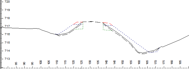
The figure below shows the resulting skewed cross section.

Figure 10 – Skewed cross section
Now you can create as many sections as you wish by moving the section feature or by creating new draped features. The following Multi-plot output shows four section features, each in it’s own Profile window (procedure not covered in this example).

Figure 11 – Multiple sections created from the same model.
21.Choose menu File | Exit. Do not save changes.