Vertical Curve Details
Updated August 22, 2024
This article applies to:
- RoadEng Civil
- RoadEng Forestry
This Knowledge Base article is an excerpt from one of our tutorial files. The files referenced in the article, as well as the full tutorial document, are available in our Tutorial Installer.
In this exercise, we will examine the Vertical Curve Panel in detail.
Note: Refer to Getting Started section for file install folders (<RoadEngCivil> and <Defaults and Layouts>).
In Location,
 File Button | Open <RoadEngCivil>\Location\Align stage 4.dsnx.
Use the Screen Layouts tool bar control to retrieve <Defaults and Layouts>\training\training Curve V.dlt.
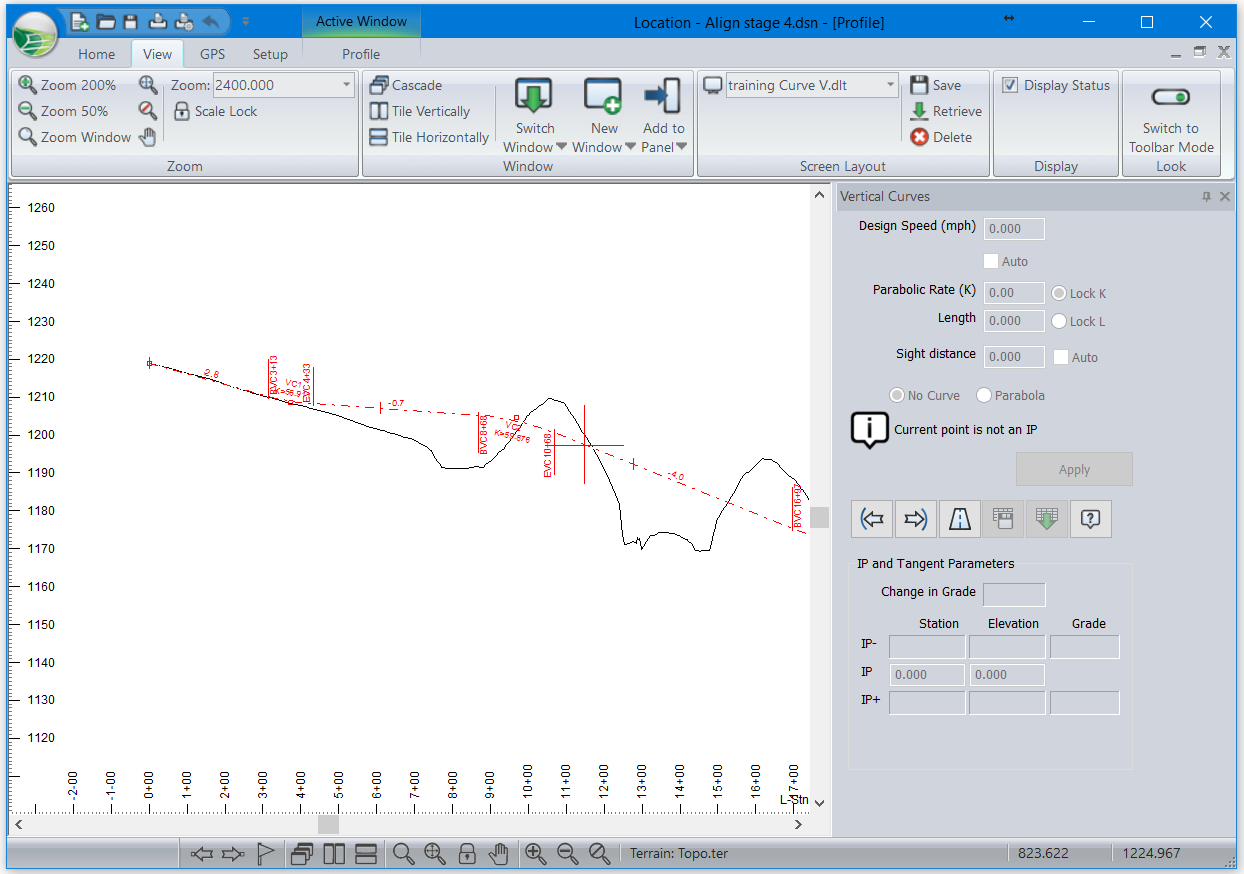
Your screen should look like Figure 16‑1.

Figure 1: Vertical Alignment with Docked Vertical Curve Panel
Use the Previous IP
 and Next IP
  buttons within the vertical curve panel to move to the first vertical curve.
Automatic Curvature
This curve has been configured to find the smallest possible curve that has a safe sight stopping distance. Enable the Auto check box Sight distance and check Parabola button.
Change the Design Speed to 30. Notice how the sight stopping distance drops, as does K and the length of curve.
Set the Design Speed back to 40.
Press the Road Class Specifications button
 to open the dialogue box shown below.

Figure 2: Road Class Specifications Dialogue Box
When Sight distance (stopping) is automatic in the vertical curve panel, it is calculated from the steepest grade in the curve and the following values from the Road Class Specifications:
Design Speed
Reaction time
Deceleration
When curvature, K, is automatic in the vertical curve panel, it is calculated from the required Sight distance and the following values from the Road Class Specifications:
Eye Height
Object Height
Type <F1> for more information.
Press Cancel to close the Road Class Specifications dialogue box.
Right Click in profile window, select Add/Edit IP Tool>move cursor to capture the VIP point for this curve. In the profile window and move it up and down. Notice how the values in the curve panel are kept up to date. With the curvature set to automatic, both the length and the curvature (K) change as the VIP is moved.
Locked K
Clear the Auto check box below the design speed. Make sure the Lock K button is selected and press Apply.
Repeat the experiment from step 10. Now the K value is constant and the length changes as you move the VIP up and down. Notice that the “K is too small for desired sight distance” warning appears and disappears (larger grades require longer stopping distances and therefore larger K values).
Locked Length
Select the Lock L button and Apply your change. Again, capture the VIP and move it with the mouse. Curves with constant length will never bump into one another when you raise or lower the VIP; however, the curvature changes dramatically.
 File | close. Do not save changes.