Bridge Site Design Using the Terrain Module Grading Tool
Updated September 12, 2017
This article applies to:
- Terrain 3D
- Terrain Forestry
- RoadEng Civil
- RoadEng Forestry
Unlike the Location module, the Terrain module can create surfaces that do not follow a linear alignment. You can create new surfaces with the Grading tool.
Northern Abutment
We’ll start by creating a road surface in a new Terrain.
1. In the Terrain module, choose File button | New.
2. Draw or import your road surface at the correct elevation up to the abutment; make it a closed polygon.
See example file North 1.terx.

Figure: Terrain with road surface polygon (only) in foreground.
 Figure: Grading Options
 Figure: Result from Grading
4. Save the Terrain created above - File button | Save (see example file North 2.terx).
Southern Abutment
We’ll do the other abutment in a new Terrain; it is easy to combine them later. In this case we will use a ballast wall so the abutment can be closer to the stream. This will require some extra steps:
- Create a surface representing a ballast wall.
- Insert the wall into a Terrain and adjust the size, location and angle.
- Build a foundation for the wall.
- Merge the wall/foundation into the original ground Terrain.
- Draw or import the road surface in a new Terrain
- Grade down to the ground will wall composite created above.
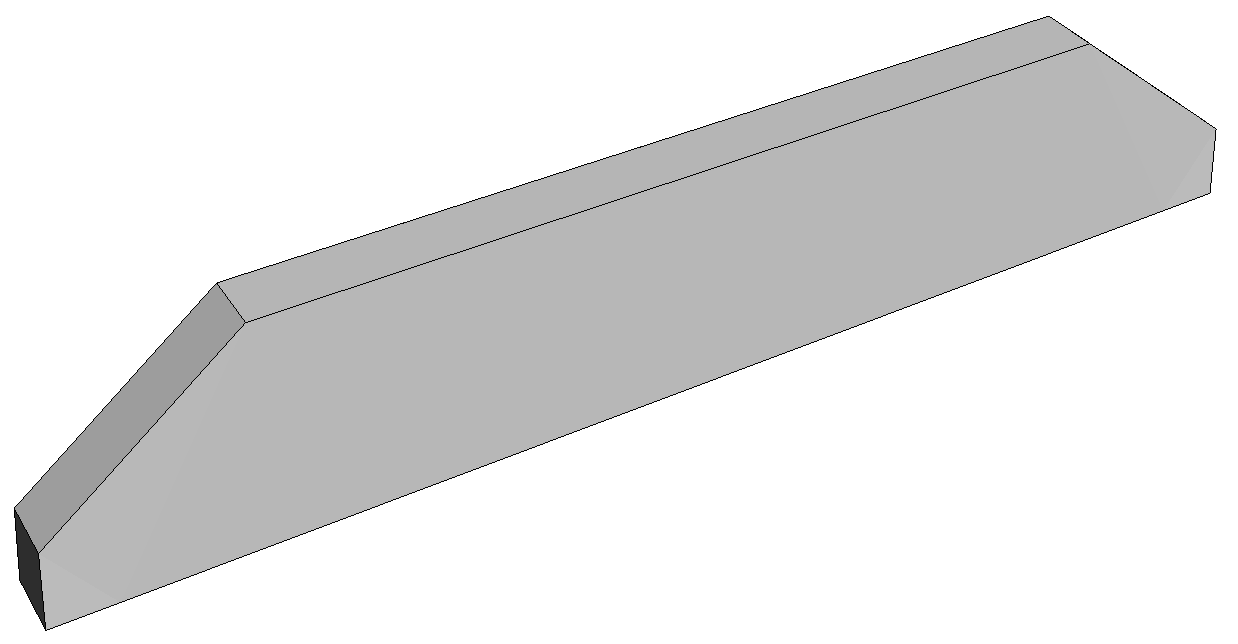
The ballast wall has already been created. We will size it and move it into the correct position.

Figure: Ballast Wall 2.terx
1. In the Terrain module, choose menu File button | New.
2. Again, put the original ground in the background. In the Plan window, select Plan tab | Window Options | background tab. Select your original ground terrain file and press OK.
3. Use menu Home tab | Insert to insert Ballast Wall 2.terx. You will be prompted with a projection dialog, update to your projection, or if you are using the tutorial files, press OK to leave it undefined.
- Zoom extents (View tab | to see both the new features and the background.
- Use Move/Size <Ctrl-M> and the mouse to move the wall to the areas of interest.
- Zoom in.
The wall is aligned East/West so it is easy to change the dimensions.

Figure: Ballast wall after insert in Move/Size mode.
4. Adjust the wall for this application.
- Make sure that all wall features are selected (they are named B-Wall* to make this easier when the Terrain is more crowded).
- Use the mouse in Move/Size mode to adjust thickness or length OR, use Feature Tools tab | Transform. Select the Rotate/Translate/Scale tab within the Coordinate Transformation dialog to adjust all dimensions including height (Scale factors).
NOTE: You can also adjust the height of the wall by lowering or raising the base feature. This is a bit tricky because you need to re-attach the corner breaklines.

Figure: Rotate/Translate/Scale dialog box.
- We need a bigger wall: Scale X=1.5, Scale Y=1.5, Scale Z=2.
- Do the Rotation in a separate Rotate/Translate/Scale operation. About 7 degrees CCW.
- Move the wall to the correct (x, y) location (roughly)
5. Adjust the elevation of the wall:
- Select the top of wall feature (B-Wall top)
- Now drag a window to select all the wall features.
- The top feature contains the current point and all features are selected; you are now ready to use the Feature Tools tab | Shift function to adjust the elevation:

Figure: The Shift operation allows you to set the coordinates of the current point and move all selected features along with it.
The Ballast wall is now hanging in space above the edge of the stream.

Figure: The Ballast wall before grading (it was necessary to build the TIN surface to create this image) as shown in the 3D window.
We now need to extend the wall down to the ground. We can extend the wall with a near vertical grade or we can use another angle to represent riprap or similar material under the wall. We will do the latter.
6. Grade the bottom of the wall to the ground. Terrain Modeling tab| Grading.
- Select the bottom of the wall (B-Wall base)
- Grade at 100% to the original ground.

Figure: Grading dialog
The first attempt indicates that the wall is too close to the stream and perhaps at the wrong angle.

Figure: The foundation for the wall is spilling into the stream.
7. Move and rotate the wall. Repeat steps 5 & 6 until you are happy with the location of the toe of the wall foundation.

Figure: The wall and foundation in a better location
In the next few steps we will create a composite surface.
8. Save the Terrain created above (see example file South Abutment 2.terx).
9. Create a composite surface.
- Open the original ground (OG3.terx).
- Merge in the wall and foundation file (South Abutment 2.terx).
- Re-calculate the TIN surface.
- Save As with a new file name (see example file South Abutment 3.terx).
Now we’ll create the road and associated fill. This is similar to the North abutment.
10. In the Terrain module, choose File button|New.
a. Put the composite surface created above in the background (example file South Abutment 3.ter).
11. Draw or import your road surface at the correct elevation up to the abutment; make it a closed polygon. It should match the elevation of the wall.
See example file South Abutment 4.ter.