Importing DWG or DXF Files
Updated May 08, 2025
This article applies to:
- Terrain 3D
- Terrain Forestry
- RoadEng Civil
- RoadEng Forestry
This Knowledge Base article is an excerpt from one of our tutorial files. The files referenced in the article, as well as the full tutorial document, are available in our Tutorial Installer.
Cadastral Survey Example
The Terrain Module will read basic geometric information from DWG files (some 'esoteric' drafting entities such as text leaders are ignored -- a log file indicates entities that are ignored). More information about the technical aspects of DWG files can be found in the On-line help.
Note: See Getting Started section for file install folders (<Terrain> and <Defaults and Layouts>)
-
 File | Open. Change file type to Autocad DWG (*.dwg).
Select <Terrain>\Import\municipal.dwg. Press Open.

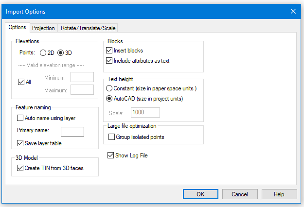
Figure 1: Import Options Dialogue
For on-line help descriptions for each of the dialogue box items, press F1 while the Import DWG/DXF Options dialogue is still active.
The options in the Text Height group box allow you to control the text size when importing the DWG file.
-
If Constant is selected, the text size is based on the drawing scale entered in the Scale field.
-
If AutoCAD is selected, the text size is determined by the scale of the drawing. Changing the scale will resize the text. Select this one it is the best option to correctly size text.
-
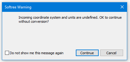
Set the dialogue options to match those shown in figure and press OK. You will get the warning message “Importing coordinate system and units are undefined. OK to continue without conversion.” Press Continue. Another warning message such as ‘unable to import 42 ArDbLeader’ click OK.


Figure 2: Softree Warning Messages.
-
After the import process is complete press View | Zoom Extents button. A city map with all the features selected will appear. De-select all features by clicking in a blank area of the Plan Window.
-
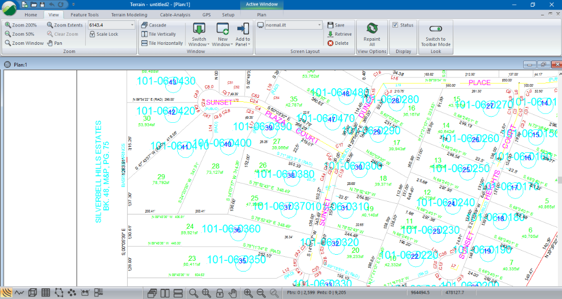
View | Zoom Window. Draw and rectangle with the mouse, this will zoom in to that specific area and allow you examine the details of the legal plans as shown in the figure below.
Note: If Primary Name (from the DWG Import Options dialogue box) is left blank, the incoming features will have their Alphanumeric ID set to the 1st 8 characters of the DWG layer name. The Numeric ID will be automatically generated.

Figure 3: Imported DWG file after Zoom Window
Note: 2D vs. 3D DWG Files
DWG files are often only 2D and thus they can't be used to create 3D models. This is the case with municipal.dwg. If you click on a feature in the Plan window you will notice in the Status window the Elevation is reported as -9999, indicating that it has no elevations. Sometimes DWG files contain a mixture of 2D and 3D entities. If these files are to be used for 3D modeling, the different feature types must be selected and their property set to 2D or 3D accordingly.
-
 File | New. Do not save the changes.