3D Window with Plan View Drape
Updated March 24, 2025
This article applies to:
- Terrain 3D
- Terrain Forestry
- RoadEng Civil
- RoadEng Forestry
Please download the associated files to go with this example:
3D Window with Plan-View Drape
Terrain Tools is not a sophisticated 3D rendering program, however, it is capable of producing reasonably good 3D visualizations for public and client presentations. This example will illustrate how to 'drape' the plan window over a 3D model.
It should be noted that the quality of the 3D rendering is determined largely by the quality of the terrain model and the image.
Draping the Plan Window.
1. Open Terrain Module. Select menu File | Open and choose file FG.terx (included with this example - see top for file link).
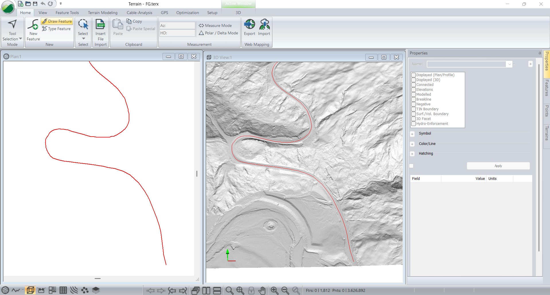
Figure 1: FG.terx - LiDAR Based Realignment
Note: FG.terx is a road realignment. The original survey was based on LiDAR. The new alignment was designed using RoadEng. From the completed design a terrain file was created and merged back into the original ground surface. The procedure to do this is described in the Creating a Post Design Surface example.
The original survey came with an aerial image which we will drape over the our 3D view to give make it more realistic.
2. Select menu File | Insert and choose All supported files in the combo box in the lower in the lower right corner. Choose M21.tif (included with this example).
3. The Select Option dialog will show up. Select Image Files and press OK.
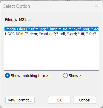
Figure 2: FG.terx - TIF Import: Select Option dialog
Note: M21.tif has been georeferenced and should appear in the spatially correct position in the terrain file.
4. When the Import Options appears set the Image Quality to high. Press OK.
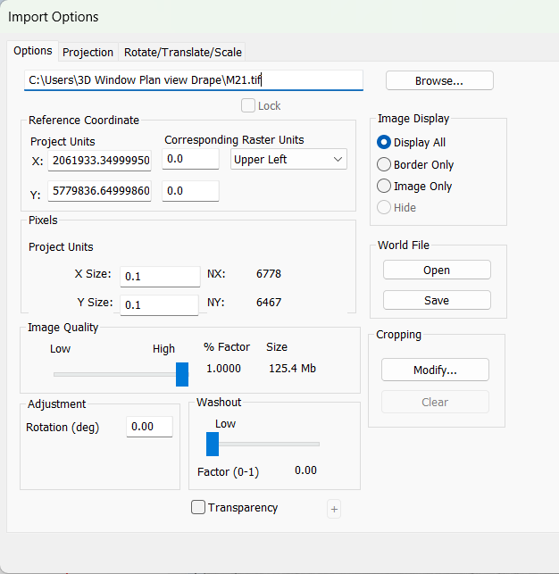
Figure 3: FG.terx - Image Import Options
5. Apply the Transformation when the Confirm Coordinate Transformation dialog prompts.
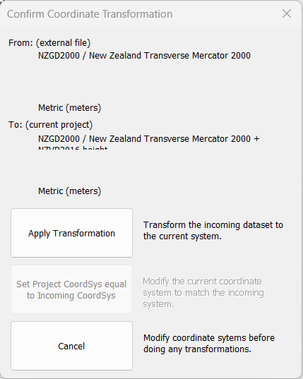
Figure 4: FG.terx - Confirm Coordinate Transformation.
The Terrain Screen should appear as shown below.
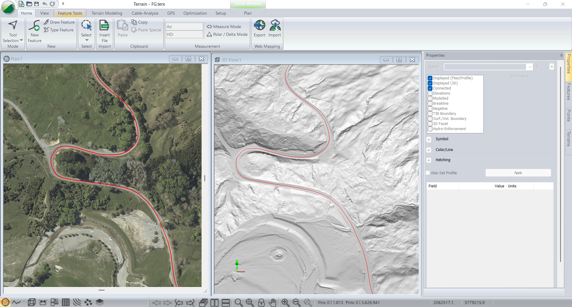
Figure 5: FG.terx with Aerial Image
6. Click on the 3D Window to make it active. Right click and choose 3D Options....
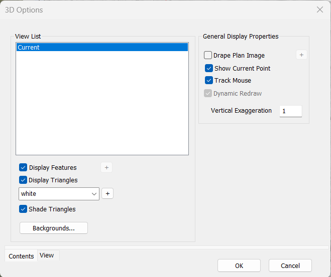
Figure 6: 3D Options
7. Enable Drape Plan Image checkbox and click on the "+" button beside it to activate the Plan View Drape Options. Set the Drape Quality to the highest quality as shown in the figure below. Press OK twice.
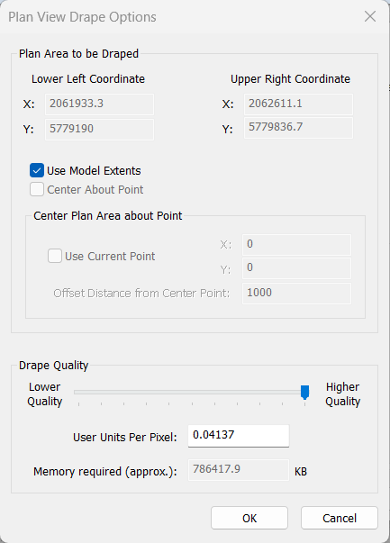
Figure 7: Plan View Drape Options
When the 3D window re-calculation is complete, it should appear as shown below.
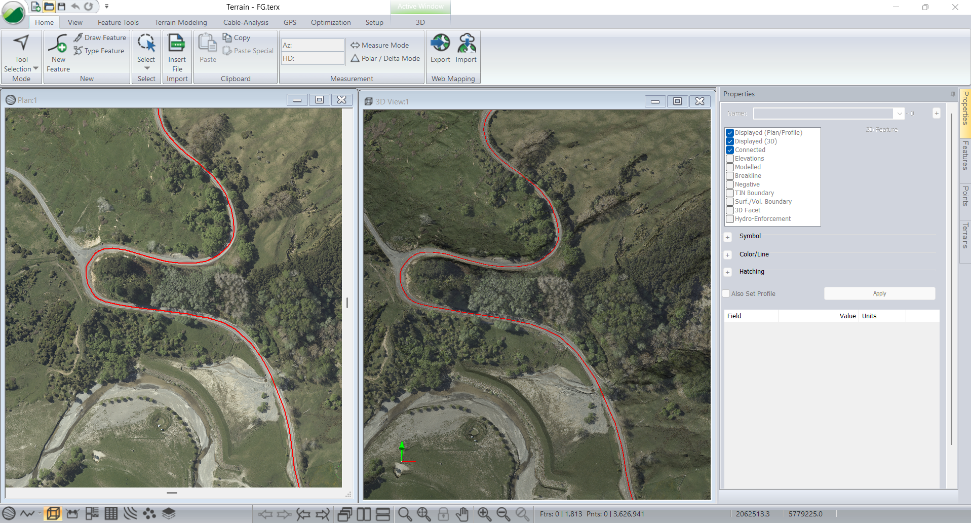
Figure 8: Plan Window and 3D Window with Plan View Drape
To complete this example, we will overlay some shapes on the 3D image.
8. Select menu File | Insert and choose Shapes.terx (included with this example). When the import options dialog appears accept the defaults.
9. Right click in the 3D window and choose menu Update 3D Display lists. The screen should appear as shown below.
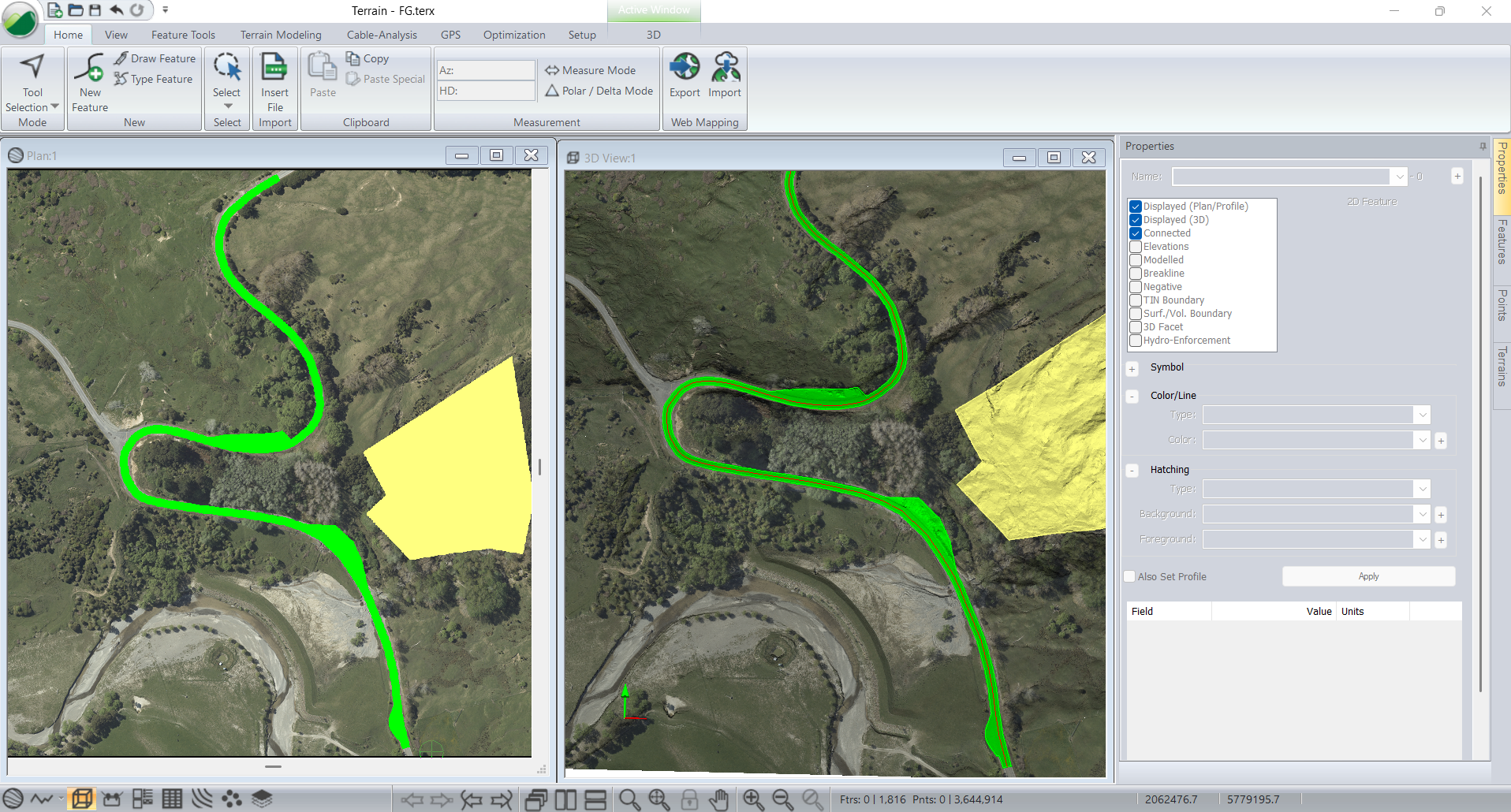
Figure 9: Plan Window and 3D Window with Image and Shapes
10. As a last example, let's delete the shapes to display and see clearly the streams and ponds of the project. Left-click to select them and use the keyboard to delete them.
11. Select Terrain Modelling ribbon. Use the Hydrology drop-down list to select Streams & Ponds.
12. In Streams & Ponds dialog, set the parameters for depression Fill Depth, Minimum Pond Area and Stream Drainage Area as shown below and press OK.
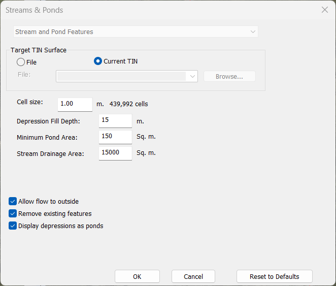
Figure 10: Streams & Ponds dialog.
13. You'll have a result similar to Figure below.
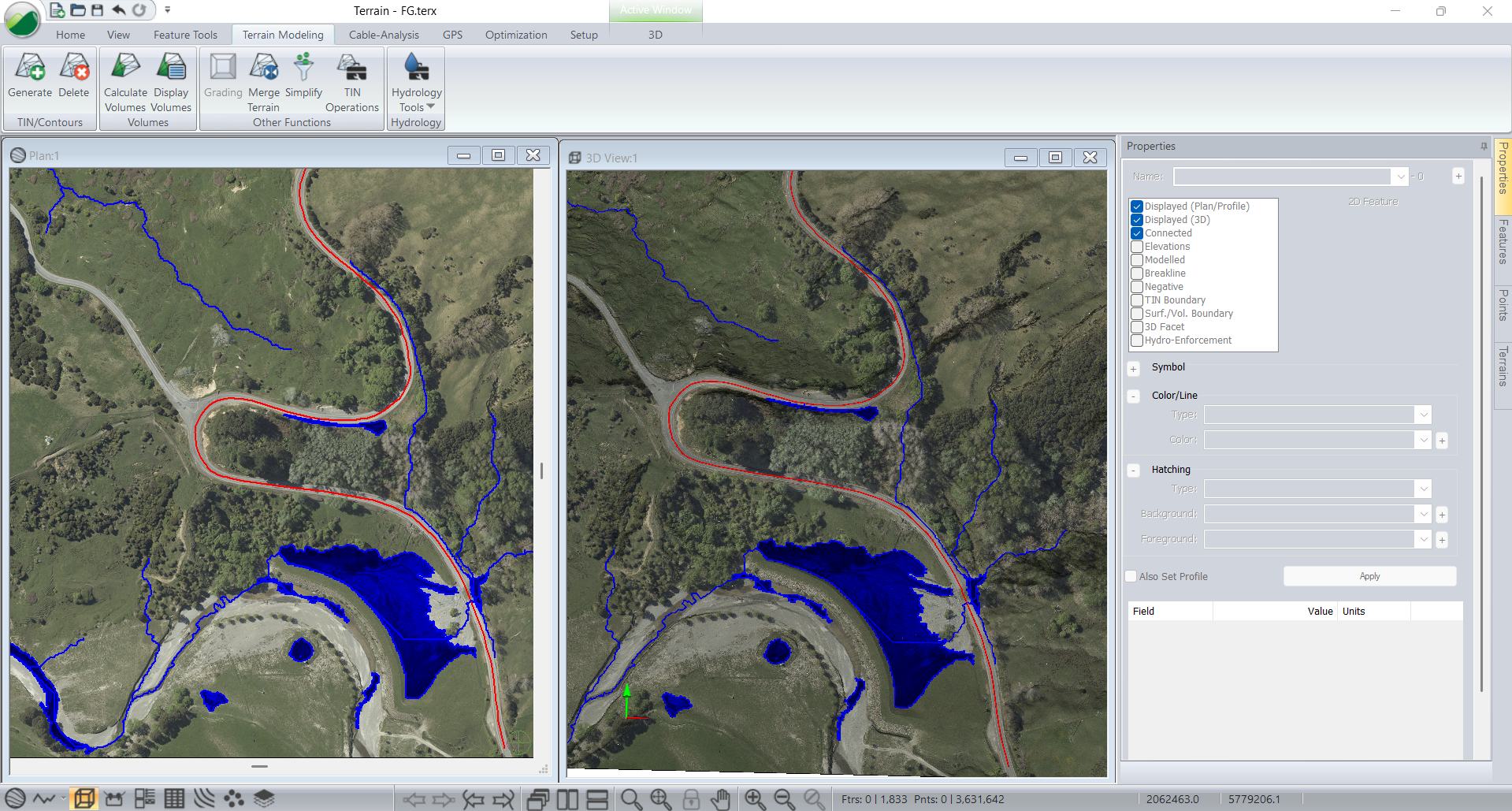
Figure 11: Streams & Ponds features displayed in Plan & 3D Window.
14. Close Terrain and do not save changes.