Calculating Volumes Using Two Surfaces: Rock Quarry Example
Updated May 08, 2025
This article applies to:
- Terrain 3D
- Terrain Forestry
- RoadEng Civil
- RoadEng Forestry
This Knowledge Base article is an excerpt from one of our tutorial files. The files referenced in the article, as well as the full tutorial document, are available in our Tutorial Installer.
Cut and fill quantities can be computed between any two triangulated surfaces or one surface and a TIN Boundary (another polygonal boundary can also be included to restrict the calculation to a specific area). Applications of this facility are numerous and include site design, stockpile and as-built quantities. To illustrate the concept, a rock quarry and a stockpile example will be done. The rock quarry example demonstrates volumes of material excavated using two surfaces and the stockpile example demonstrates volumes using only one surface.
Rock Quarry Example
 File | Open <Terrain>\DTM\original ground.terx.
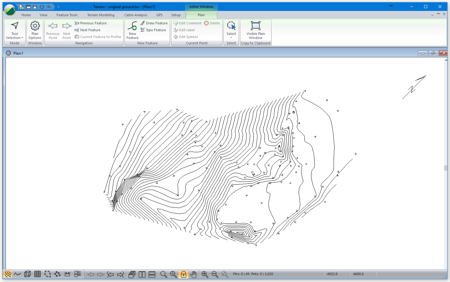
Original ground.terx was created from a total station survey of a rock quarry. The XYZ coordinate points were imported, a triangulated surface and corresponding contours were generated and saved in a Terrain file (original ground.terx)
After the rock was removed from the quarry, another survey was done and again imported, triangulated and saved in a second Terrain file (excavation.terx).
|
Figure 1: Original surface |
Figure 2: Surface after excavation (excavation.terx) |
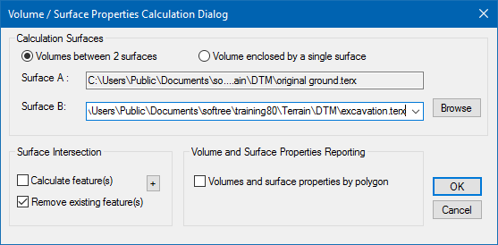
- Terrain Modeling | Calculate Volumes. This will activate the dialogue box below.

Figure 3: Volume / surface properties calculation dialogue
Note: To calculate volumes via this method, you must have created 2 terrain models and saved them in separate files. The first terrain model (surface A) is always the current Terrain.
The Terrain Modeling | Calculate Volumes is disabled if the current file does not have a terrain model. The user specifies the other surface (surface B) in the Volume / Surface Properties Calculation dialogue box.
- Press the Browse button opposite Surface B. Select <Terrain>\DTM\excavation.terx. Press Open. Surface A should be set to original ground.terx and surface B should be set to excavation.terx. The order of these surfaces is not important as you will see later.

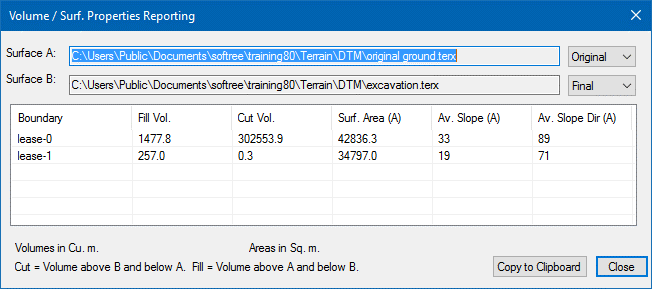
Figure 4: Volume / Surf. Properties Reporting Dialogue
- Press Close.
The following steps demonstrate how to include two polygonal boundaries and calculate the volume inside each one.
- Home | Insert File. Select and open <Terrain>\DTM\boundary.terx. Open button. The Import Options Dialogue box appears. Press OK.
- Softree Warning may appear, select do not display again. Press OK.
Two boundary polygons should now be visible in the Plan Window as in the figure below. If not visible press the Zoom Out ![]() button on the tool bar.
button on the tool bar.

Figure 5: Original Topography with Boundary Polygons
- Open the Feature Properties panel
 . Enable Surf/Vol. Boundary. Press OK.
Note: When a feature has surface / volume boundary set volumes, surface area, slope and slope direction will be calculated and assigned to the feature as attributes.
- Terrain Modeling | Calculate Volumes button to open the Volume / Surface Properties Calculation dialogue box shown in below.

Figure 6: Volume / Surface Properties Calculation
Dialogue - Volumes by Polygon
- Check Volumes and surface properties by polygon and ensure all other selections are as indicated in the figure above. Press OK to begin the volume computation.
When completed, the Volume/ Surf. Properties Reporting dialogue box will appear (figure below). If you are working in imperial units (feet) the volumes will be reported in cubic yards.

Figure 7: Volumes/Surf. Properties by Polygon
Note the cut, fill quantities and surface properties are reported for the 2 polygons (lease-0 and lease-1).
- Press Close. To view the values again, create a status window by Terrain Modeling | Display Volumes button. Close window.
Volumes can also be viewed in the status portion of the Feature Properties panel.
- With the boundary feature selected. Attributes can be added if you press the
 button at the base of the Feature Properties panel and press the Add/Remove… button. Change the Selected items list to include only Area, Vol. above and Vol. below (the latter two can be found in the Surface Properties folder).

Figure 8: Add/Remove Items to Status Window
- Press OK twice to return to the main screen.
- The Status portion of the Feature Properties Panel displays the volumes associated with each lease feature. Select each lease feature and see how the volume changes.
- To finish this example the results will be exported to a Microsoft Excel® spreadsheet using the Windows Clipboard. If you do not have a similar spreadsheet you can skip the next 2 steps.
- Terrain Modeling | Display Volumes button. The Volume/Surf. Properties Reporting dialogue box will appear, then press Copy to Clipboard button.
- Open Microsoft Excel® and create a new (blank) document. With the cursor positioned in the first cell select menu Home | Paste.
The volume information should appear as in the figure below:

Figure 9: Volume Report Exported To Microsoft Excel®
- Close your spreadsheet. Close Volume / Surf. Properties Reporting dialogue box.
 File | New. Do not save the changes.

