Creating a DTM with Contours
Updated May 08, 2025
This article applies to:
- Terrain 3D
- Terrain Forestry
- RoadEng Civil
- RoadEng Forestry
This Knowledge Base article is an excerpt from one of our tutorial files. The files referenced in the article, as well as the full tutorial document, are available in our Tutorial Installer.
In this exercise, you will open a file containing 3D data (imported in the Importing ASCII Survey Files exercise above) and create a Digital Terrain Model (DTM).
You will also generate major and minor contour lines.
Note: The digital model is represented by a Triangular Irregular Network (TIN); for this reason, menus, documentation and help files often refer to a Digital Terrain Model as TIN model.
Open the Terrain Module.
 File | Open <RoadEngCivil>\DTM\Topo 1.terx. Remember you need change the file type to Softree-Terrain (*.terx) in the dropdown menu.

Figure 1: Terrain file Topo 1.terx
Terrain Modeling | Generate TIN. This opens the dialogue box depicted.

Figure 2: Digital Terrain Calculation Dialogue Box with
Both Major and Minor Contours Enabled.
Contour Specification
Ensure the Labeling box is checked in the Major Contours tabs. Clicking on the
 button adjacent to the Major or Minor Contours check boxes, allows you to change the color and line type used for the contour lines. Optional contour Smoothing (controlled by Thinning distance) rounds the corners where contours cross triangle sides – smoothed contours do not match the model elevation exactly.
Note: Default contour line types and colors are stored in the Normal.ilt screen layout. Any changes made after a new document is created are saved with the document.
Click on the Major Contours tab and set the Interval: 10 and check the Labeling box as shown above. You also need to an even number before the start of calculated range. Set the elevation Start: 1150.

 Click on the Minor Contours tab and set the Interval: 2 and make sure Labeling box is unchecked. You also need to set the Start elevation to be a multiple of 2. Start: 1150.Press OK to generate both TIN and contours.
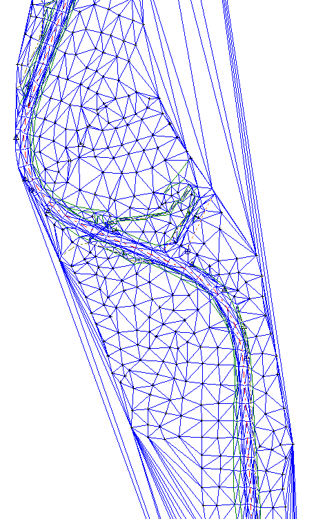
Figure 3: Contours Generated without Boundary or Length Limitation. Underlying Triangles Shown on Right
Figure 4: Terrain Modelling | Delete TIN | select Delete Contours box | OK. Right click in plan view select Active Window (Plan) Option…| Surface tab | check Triangle outlines box.

Figure 5: Contour Formation from TIN model. Elevations between known Elevation Points are Interpolated. Enabling Contour Smoothing causes Contours to be Less Angular
Limiting Triangles
In this example, the triangles (and resulting contours) on the upper right and lower left of the model are unrealistic – elevations are being interpolated between points very far apart. There are two ways to prevent these unrealistic triangles:
-
Create a boundary polygon (with property TIN boundary).
Limit triangle length.
A boundary polygon will limit triangle formation to an area of interest – this can also be useful when your data set is very large or when you wish to merge a small DTM into a larger one. TIN boundaries will be covered in other exercises.
In this example, we will limit the triangle length.
If triangles are still displayed, turn them off: Right click in plan view | Active Window (Plan) Options… | Surface tab | uncheck Triangle outlines box | OK.
Terrain Modeling | Generate TIN. This re-opens the Terrain Calculation dialogue box.
Check Calculate triangles box, un-check Include all and set the Maximum side length: 150 (see Figure 7‑5).
Note: Maximum side length of your triangles should be set as small as possible to create an accurate TIN. However, if you set this value too small, there will be holes in your model. As a rough guide LiDAR data could use a triangle length of 50 or smaller. A trial and error approach can work for this. Put in a number, generate the 3D model and if the model has “holes” in it, increase the side length.

Figure 6: Terrain Calculation with Triangle Maximum Side Length Limited
Press OK to recalculate triangles and contours. Your Plan window should look like the figure below.

Figure 7: Terrain Model with Triangles Limited to 150 feet
At this point you may wish to experiment with some of the other options in the Terrain Calculation dialogue box. Once the dialogue box is open type <F1> to see detailed help information.
 File | Save As, this opens the file Save-As dialogue box. Notice that the default folder is the RoadEng Settings and Layouts folder. Cancel to close the dialogue box; we will not save this table.
 File | New. Do not save changes.