Improving Contouring with Breaklines
Updated May 08, 2025
This article applies to:
- Terrain 3D
- Terrain Forestry
- RoadEng Civil
- RoadEng Forestry
This Knowledge Base article is an excerpt from one of our tutorial files. The files referenced in the article, as well as the full tutorial document, are available in our Tutorial Installer.
Site Survey Example
Identifying and modeling breaklines can significantly improve the accuracy of a TIN model and associated contours. Breaklines are sharp changes in ground slope such as a creek bank, an edge of a road, an edge of ditch or a rock bluff.
Triangles should not be allowed to form across these features, since doing so would flatten the slope across the break. Features in the Terrain Module will be used as breaklines when their Breakline property is enabled. Triangle link lines will not cross Breakline features.
This breakline example uses a topographic survey around a creek. The data was created and adjusted in the Survey/Map module. See Survey/Map Tutorial - Making a Map with Multiple Traverses for more information.
 File | Open. Change Files of Type to Softree-Terrain File (*.TERX).
- Select <Terrain>\DTM\breakline.terx. Press Open.
- Terrain Modeling | Generate TIN button.
- In the Terrain Calculation dialogue box:
- Turn on Major Contours, Minor Contours and Smoothing.
- Check Calculate triangles, change the Maximum Side Length to 60 (there are no void areas in this model).
- Select the Minor Contours tab and change the Interval to 1.0.
- Select the Major Contours tab and change the Interval to 5.0 and turn on Labeling. Press OK.
Once the calculation is complete, a model of a creek with poorly generated contours will be displayed.

Figure 1: Model of creek with poorly generated contours
- As an optional exercise, we can view the triangle outlines that the TIN model create: Plan | Plan Options | Surface tab. Enable Triangle outlines. After looking at the triangles that represent the TIN model, turn the display off again for the rest of this example.
The plan view in the figure above has contours that show the creek bottom rising up to the same elevation as the top of the banks (scarp 1, 2). This is due to triangles being formed between the scarp features and crossing over the creek features. To correct this, the defining features are made into breaklines.
- Home | Select | By name in dropdown menu. Press Un-Select All, then select the features as shown in the figure below by double-clicking on them in the Select feature (s) by name window. Press OK.

Figure 2: Select feature(s) by name dialogue
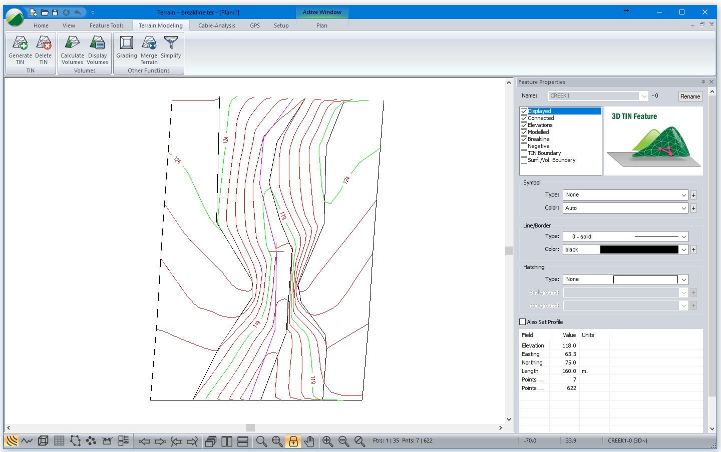
- Enable the Feature Properties Panel
 Enable Breakline.
 - Terrain Modeling | Generate TIN. Press OK to accept the settings.
After re-calculating, the contour lines now indicate a continuous gully as shown in the figure below.

Figure 3: Contours after breaklines have been set
 File | New. Do not save changes.