Creating a Cut/Fill Map
Updated May 04, 2016
This article applies to:
- Terrain 3D
- Terrain Forestry
- RoadEng Civil
- RoadEng Forestry
To run this example you will need Terrain Tools® or RoadEng® Version 5 or higher.
Terrain allows you to save data in a Regular Grid format. The Regular Grid format is a an array of points regularly spaced in plan (XY plane). A Z-value is associated with each point.
The grid is defined by:
- Origin X and Y
- Widths X and Y
- Number of node in the X and Y directions
- Azimuth (measured from north clockwise)

Figure 1: Grid Definition
Several options exist for computing the z-value including surface elevation and difference between surfaces. In this example we will save a grid using difference between surfaces to create a cut/fill map.
The example starts with 2 existing TIN surfaces:
- OG.ter = original ground surfaces
- Excavated.ter = post excavation surface
Creating a Grid File
1. File | Open. Select Excavation.ter. Press Open.
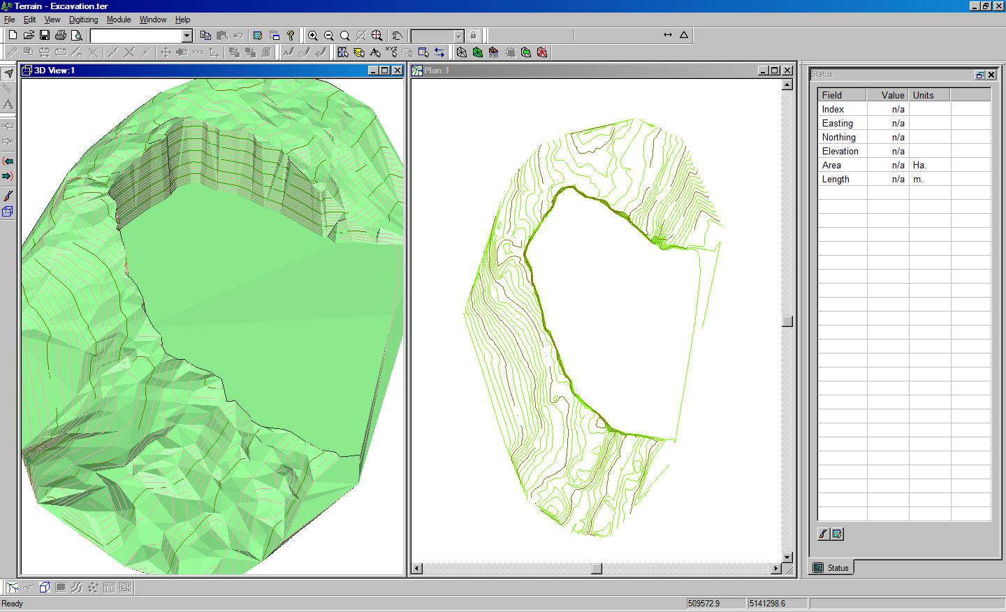
Figure 2: Excavation.ter surface after excavation
2. File | Open. Select OG.TER. Press Open.
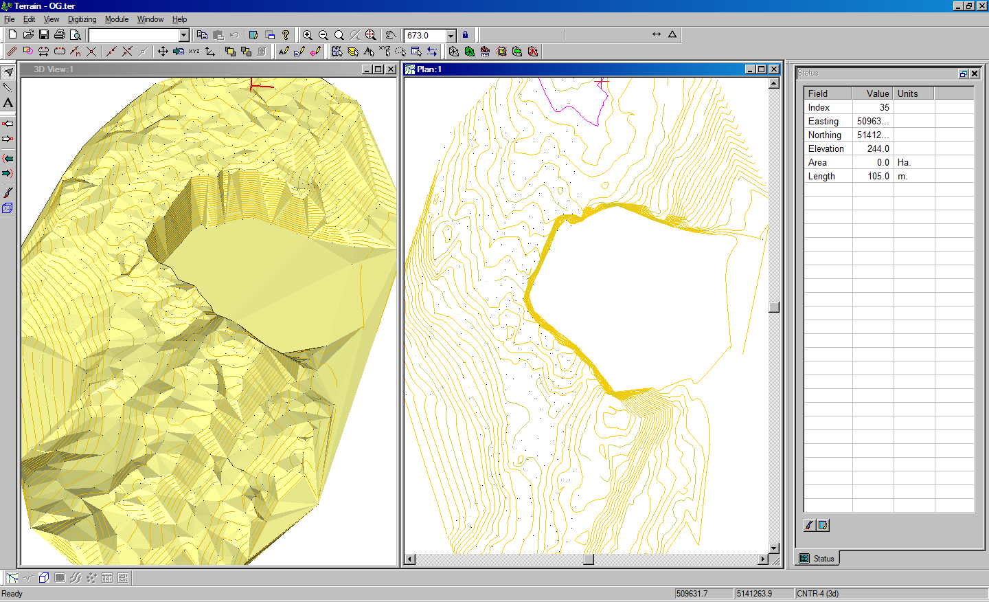
Figure 3: OG.ter – original ground surface
3. Choose menu File | Save As. Set the file name to CutFillMap.ter and set the save as type to Regular Grid (*.ter).
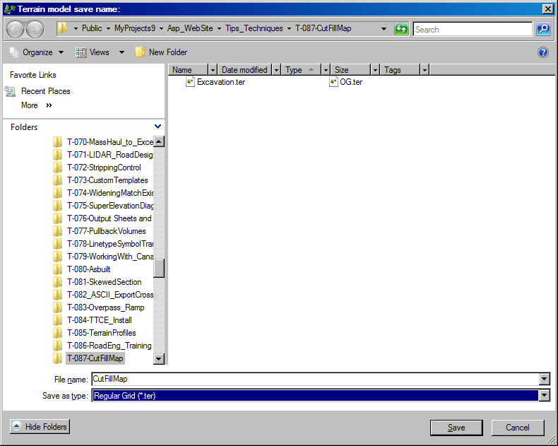 Figure 4: Save As dialog box.
4. Choose menu File | Save As. Set the file name to CutFillMap.ter and set the save as type to Regular Grid (*.ter).
5.When the Regurlar Grid options appears set the parameters as shown in the dialog below The location of surface B (Excavation.ter) will depend on where you saved the example files.
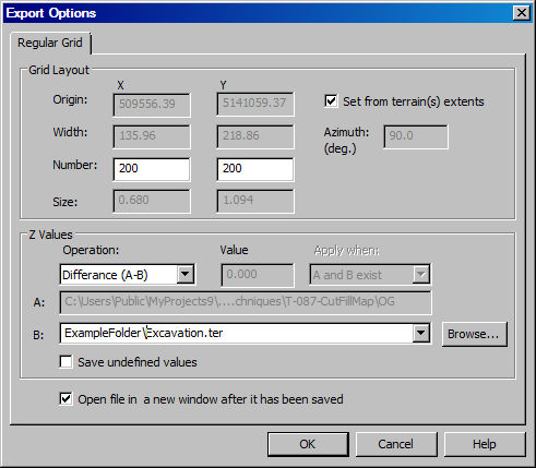
Figure 5: Regular Grid Export options dialog box.
After pressing OK the CutFillMap.ter will appear in a new instance of Terrain similar to that shown in Figure 6.
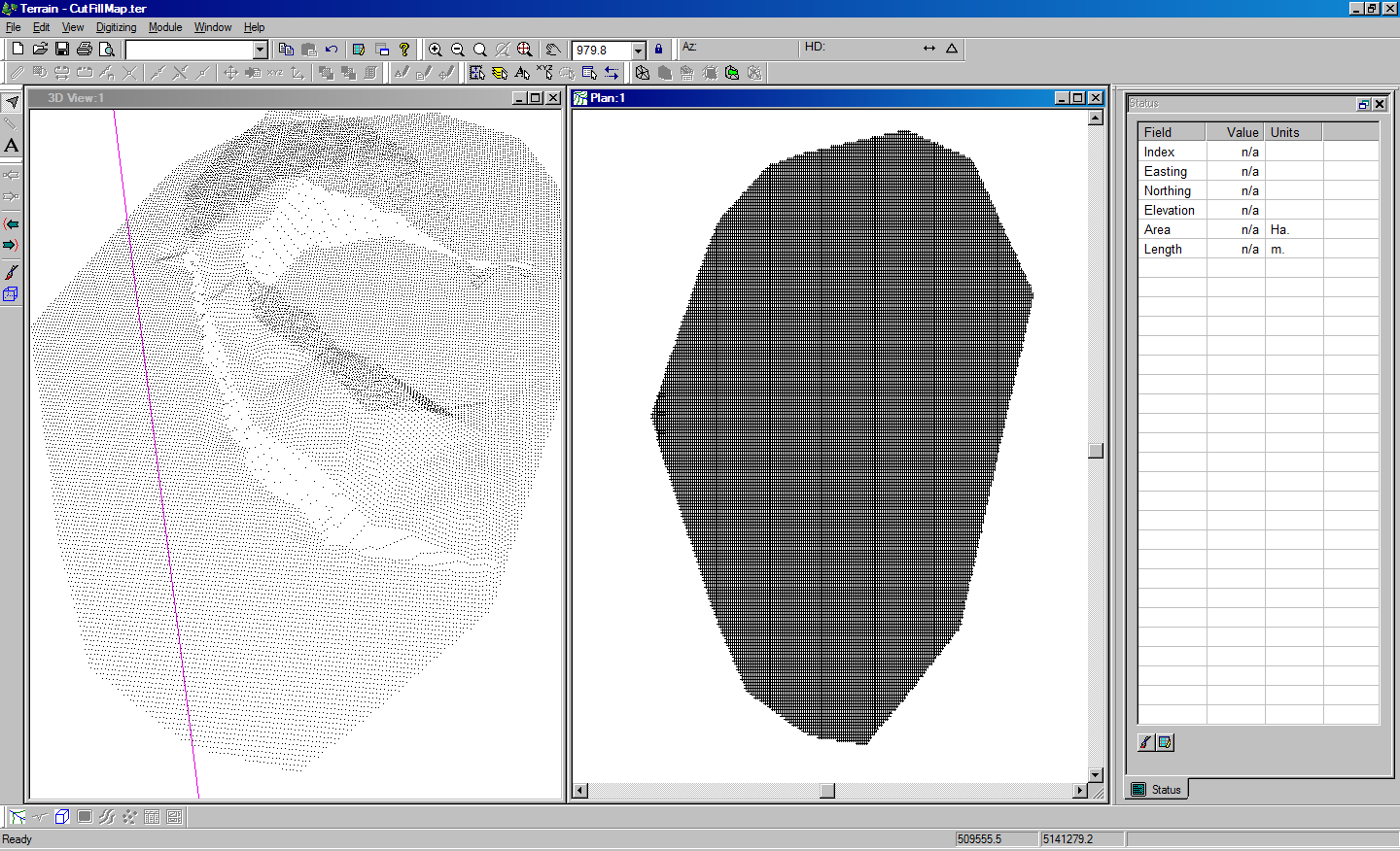
Figure 6: CutFillMap.Ter.
To complete this example try calculating a terrain model and shading (or contouring) the result. Figure 7 shows a color coded map of cut/fill depths.
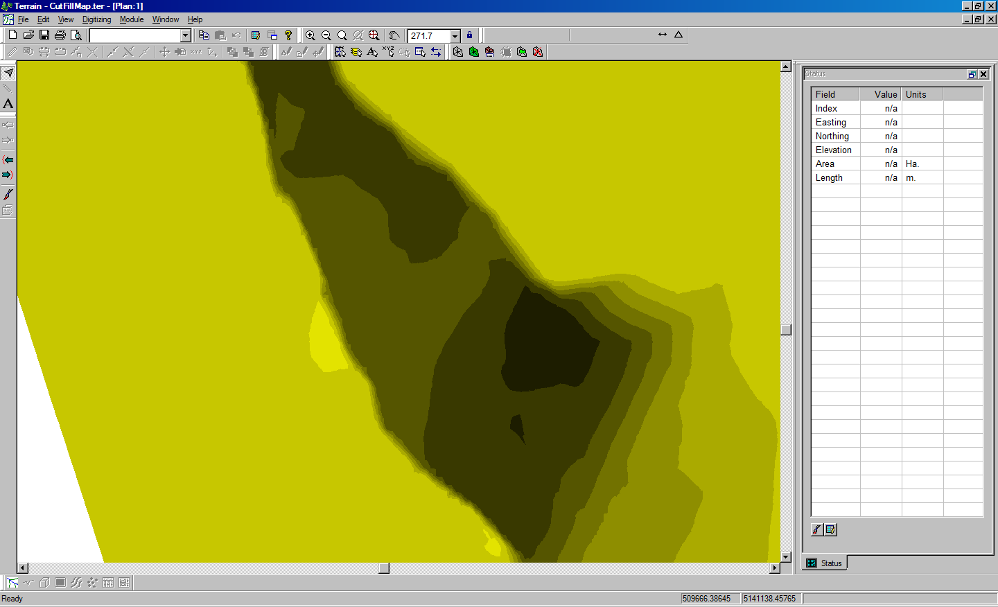
Figure 7: Color coded cut/fill map