Survey Adjustments in the Map Screen
Updated November 07, 2023
This article applies to:
- Terrain 3D
- Terrain Forestry
- RoadEng Civil
- RoadEng Forestry
This Knowledge Base article is an excerpt from one of our tutorial files. The files referenced in the article, as well as the full tutorial document, are available in our Tutorial Installer.
The map display (Method 2) provides a simpler method of implementing, undoing shifts and other adjustment functions. It demonstrates how to do adjustments without modifying the Traverse Document coordinates.
Method 2 has the following advantages over Method 1
- Opening of multiple Traverse Documents not required.
- Direct feedback on whether the adjustment worked or not, as the user is viewing the map rather than coordinates within Traverse Documents.
- The last adjustment can be undone using the Delete key in the Traverse Adjustments dialog.
 File | Open <SurveyMap>\Adjust\method2.map. Unlock Lock Scale
  by ensuring the button is not highlighted and press the Zoom Extents
  button.
The map shown in the figure below will appear.
- Maximize the window by clicking the maximize button
 on the top right of the Traverse Document window.

Figure 1: Map Document of method2.map
This example includes four traverses main, block1, spur and join.
- Select Map | Coordinates Adjustment to open the Traverse Adjustments dialog box shown below.

Figure 2: Traverse Adjustment Dialog Box
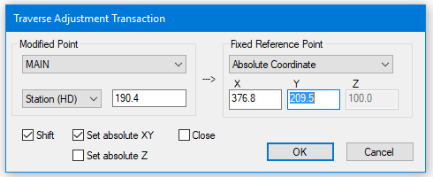
- Press the New… button, and change the information in the dialog box to match the figure 5.9. Note that both Shift and Set absolute XY is checked. Press OK and then press Apply.

Figure 3: Traverse Adjustment Transaction Dialog Box
Note that main traverse has been shifted to the set of coordinates on the Fixed Reference Point side. You may need to left click on the Traverse Adjustment title bar and drag the dialog box down and sideways to see the map changes.
Note: The absolute coordinates used in this example are local coordinates. UTM or any other coordinate system can be used.
- Within the Traverse Adjustments Dialog Box:
-
- Press the New… button.
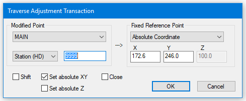
- Change the Modified Point to Main and
- Enter Modified Point Station to 9999. (9999 is end station).
- Change the Fixed Reference Point to Absolute Coordinate
- Change Fixed Reference Point X to 172.6 and Fixed Reference Point Y to 246.0.
- Ensure Set absolute XY is the only box selected.
- Press OK.

Figure 4: Traverse Adjustment Transaction Dialog Box
- A Softree Prompt “Station not found. Press YES to use nearest station (958.1). The Modified Point Station will automatically change to 958.1. Press Apply. A checkmark will appear in front of that adjustment in the adjustment list. The traverse was stretched to fit between the two sets of local coordinates.

Figure 5: Traverse Adjustment Transaction Dialog Box
- Make another Traverse Adjustment:
-
- Press New… button within Traverse Adjustments
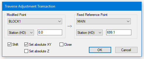
- Change Modified Point to BLOCK1
- Enter Station(HD) to 0.0.
- Change the Fixed Reference Point to Main
- With Station(HD) set change it to 699.1
- Make sure Shift and Set AbsoluteXY are selected.
- Press OK and then Apply.

Figure 6: Traverse Adjustment Transaction Dialog Box
The start of main.tr1 identified by labels “POC Block1, POC join” now coincides with the start of block1.tr1.
| Action | Modified traverse | Modified Station | Fixed Traverse | Fixed Station | Result | |
|---|---|---|---|---|---|---|
| 1 | Shift and Set Absolute XY | Main | 190.4 | 376.8 X and 209.5 Y | 0.0 | Puts main in correct position with respect to Absolute set of coordinates |
| 2 | Set Absolute XY | Main | End | 172.6 X and 246 Y | End | Accommodate second absolute set of coordinates (main is stretched). Note that “9999” is used for end station. Main is now tied to the 2 Absolute points. |
| 3 | Shift and Set Absolute | Block 1 | 0.0 | Main | 699.1 | Shifts Block1 to Main. |
| 4 | Close | Close Block1. | ||||
| 5 | Set Absolute XY | Block 1 | 681.5 | Main | 502.1 | Shift Block to position on Main |
| 6 | Shift and Set Absolute | Spur | 0.0 | Main | 657.5 | Shift Spur to position on Main. |
| 7 | Set Absolute XY | Spur | End | Block 1 | 522.0 | Attach Spur to Block1. |
Figure 7: Table Depicting Adjustment Steps
- This step coincides with Step 4 of the table above. Press New and make sure that Close is checked. Press OK then Apply. The Block1 traverse will close.
- Zoom in. Note that the “block 681.5” and “main 502.1” do not coincide. Block1 needs to tie to main at this point.

Figure 8: Point 681.5 and 502.1 Not Coinciding
- Adjust Traverse to make points coincide:
-
- Press New… and turn off Close option.
- Change the Modified Point Traverse to BLOCK1 and Station (HD) to 681.5.
- Change the Fixed Reference Point Traverse to MAIN and the Station (HD) to 502.1.
- Make sure that Shift is not checked and Absolute XY is checked. Press OK and then Apply.
- “block 681.5” and “main 502.1” now coincide.
- Follow the above procedure to complete steps 6 and 7 of table above. The two figures below should provide some guidance.

Figure 9: Method2.map Before Adjusting spur.tr1

Figure 10: Method2.map After Adjusting spur.tr1
At this point all traverses except join have been adjusted. This operation is similar to that for spur. Keep in mind the final position of join in shown below.

Figure 11: method2.map After Adjusting join.tr1
Note: Only coordinates and absolute points are modified by adjustments. Raw traverse data (Azimuth, Distance, Slope, etc…) are unaffected. All adjustments can be removed by pressing the Delete or Clear All buttons in the Traverse Adjustment dialog box.
Adjustments can be independent or dependent on previous adjustments. It all depends on the order of operations. The last operation in the list supersedes previous operations for that traverse. For example, move the end of main to a different location.
- Add New Traverse:
-
- Press New…
- Change the Modified Point to MAIN and station to 958.1.
- Change the Fixed Reference Point Traverse to Absolute Coordinate and the Fixed Reference Point Station to X = 376.8 and Y = 209.5.
- Make sure that Shift is checked and press OK and then Apply.
You will notice that main has moved without affecting other traverses and that last operation on traverse main supersedes the previous operations.
To move other traverses with main simply change the hierarchy of the last operation.
- Using the Shift up button, move last operation so that it is just above the operation:
block1 0.0 Shift/Set XY main 699.1 - Press Apply.
- Now press the Delete button and press Apply. The Traverse Adjustment will look like the figure below. Because the previous main adjustments in the list now take effect the map will look like Figure 10.

Figure 12: method2.map After Adjusting join.tr1
Note: All adjustments in this example were with reference to the XY direction (2D) only. 3D adjustments can also be done by turning on Absolute Z in the Traverse Adjustment Transaction dialog box.
- Close the method2.map window. Do not save changes.