Adjusting for Magnetic Anomalies
Updated July 08, 2021
This article applies to:
- Terrain 3D
- Terrain Forestry
- RoadEng Civil
- RoadEng Forestry
This Knowledge Base article is an excerpt from one of our tutorial files. The files referenced in the article, as well as the full tutorial document, are available in our Tutorial Installer.
Certain geographic locations have problems with magnetic fields that may disturb compass readings. If the foreshots to next station and the backshots from next station differ significantly, magnetic anomalies may be the problem. This example will demonstrate how to correct this problem.
 File | Open <SurveyMap>\Adjust\absazim.map and \Adjust\absazim.tr1.
- Select View | Tile Vertically.

Figure 1: Compass Errors from Magnetic Anomalies
The traverse should have been a straight line at a bearing of 0, but due to a magnetic anomaly, the traverse is skewed. The traverse is correct up to station 200. After station 200, the foreshot and corresponding backshot start to differ. Once the traverse proceeds beyond the anomaly (Station 1300), it reverts back to the initial bearing. There is a simple way of fixing this problem.
- Select the Traverse Document title bar.
- Traverse | Traverse Entry button, choose the Options… button and select the Automatic Magnetic Anomaly Adjustment check box. Press OK twice.
This automatically enables the Foreshot/Backshot Tolerance (degrees) option and the default setting of 1.00. This means that when the foreshot and corresponding backshot differ by more than 1.00 degree, there will be an adjustment to correct for the magnetic anomaly.

Figure 2: Corrected Traverse
Note: Magnetic Anomalies are corrected by using foreshot and backshot to calculate relative changes in angle (turning angles). These turning angles are used to calculate each azimuth from the previous one (similar to a theodolite survey). This works because the deflection error from the anomaly is the same for both the foreshot and the backshot taken from the same point.
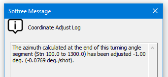
- Highlight the traverse document. Open Traverse | Adjust XYZ button. The Coordinate Adjust Log, as shown below, appears. Press OK.

Figure 3: Turning Angle Adjustment Message
This dialogue box identifies the azimuth error adjustments, when a calculated azimuth at the end of a relative segment is reconciled with an absolute azimuth. In this case the azimuth was adjusted 1.0 degree.
The symbol “ ∼ ” appears in the Station column, indicating the stations which were calculated using turning angles.
Warning: You might at some point find that the difference between foreshot and corresponding backshot = zero “0.0”, when you pass through an anomaly, as shown in the Foreshot/Backshot dialogue box below. In this case the magnetic anomaly may not be corrected automatically, and a manual adjustment of the offending station may be required.
To manually adjust a magnetic anomaly, double click on the Foreshot field to display this dialogue box shown below. Enable the Calculate Azimuth using Turning Angle and last Azimuth option.
You can also set up the Traverse Entry Options to automatically display the dialogue box by selecting Traverse | Traverse Entry Options and enable Azimuth Fore/Back shots under Automatic Extended Entry.

- Close both documents. Do not save changes.