Location Module Setup & Starting a Project
Updated August 20, 2024
This article applies to:
- RoadEng Civil
- RoadEng Forestry
This Knowledge Base article is based on one of our tutorial files. The files referenced in the article, as well as the full tutorial document, are available in our Tutorial Installer.
To create a new road alignment in the Location module, you first need to create an original ground DTM. This is usually done by reading survey data into the Terrain module, and then creating a surface with contours. However, it is possible to import DTM surfaces from other applications by using LandXML or DWG (3D faces) file formats.
Tutorial Example - Creating a Location Design from a Terrain Surface - Using Center of Terrain as a Starting Point
1. Open the Location Module. File | New File.
2. Select Terrain Surface, and press the Browse… button and open <RoadEngCivil>\Location\Topo.terx. Press OK.

Figure 1: File | New File – Opening File to Define the Original Ground
3. The Initial Alignment dialogue box will appear. This allows you to select a start coordinate or to import an existing alignment.

Figure 2: The Initial Alignment Dialogue Box
4. Choose Center of Terrain (we will define our start coordinate later).
5. Press Next >>, keep Standard Template checked. Press Done.
The look of your initial screen depends on the contents of the default Screen Layout (normal.dlt).
6. To change screen layout, select View | Screen Layout group, select layout training Normal.DLT from the training folder in the dropdown list.
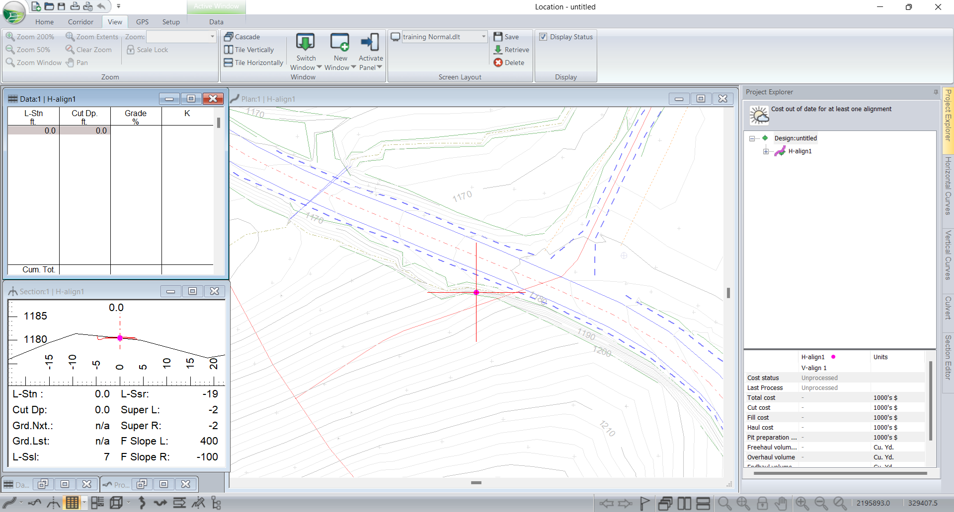
Figure 3: The Location Module after Beginning a New Alignment
The red line in the figure above depicts the proposed new alignment, mostly to the left of the old road. You can see the original ground DTM in the Plan background; the line work is faded so it doesn’t overwhelm the new alignment features.
The shape (road dimensions) of your cross section depends on the contents of the default Template table (Normal.TPL) in your RoadEng <Defaults and Layouts> folder. The next few steps will load templates for this exercise.
7. Home | Templates. This will open the Template Editor.

Figure 4: Template Editor Dialogue Box
8. Within Templates Editor, press Open Table, select <Defaults and Layouts>\training\training Normal feet.tpl. Open.
9. If you are working on a training computer or if you have not yet configured your default templates, you may wish to save template: Save Table | all selected, press OK | over-write Normal.TPL | say Yes to replace existing. Note that templates depend on length units (feet or meters).
10. OK to close the Template Table Editor. OK to recalculate the cross sections. Templates will be discussed in more detail in future exercises.