Step 3 - Run the Digital Planting Tool
Updated April 16, 2026
This article applies to:
- Terrain Forestry
- RoadEng Forestry
Regardless of the workflow you’ve followed, we now have polygon features that we will use to calculate rows that support machine operability for planting and/or thinning. In both cases we will use the aspect polygons and “auto” setting to generate rows that follow the slope of the terrain. For workflow B, we’ll additionally manually set row directions for the polygons that represent flat areas.
Workflow A: Only Consider Aspect
- Open Workflow A – Step 3.terx, or continue with the files from the previous step associated with workflow A.
- Select Aspect Polygon
- Use Select Feature by Layer.
- Choose the Feature Aspect Ranges layer.
- Select Aspect Polygon
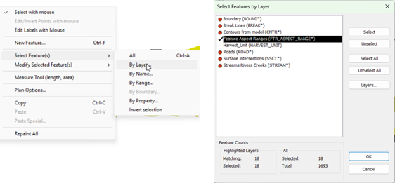
Figure 21 - Selecting Aspect Polygons
- Click OK (you’ll see how many aspect polygons were selected).
- Open The Digital Planting Tool
- On the Optimization Toolbar, select Digital Planting.
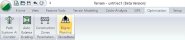
Figure 22 - Digital Planting Tool is located in the Optimization Ribbon
- Configure Planting Parameters:
- Row Spacing: 4 m
- Point Spacing (within row): 2 m
- Minimum Trees per Row: 1
- Orientation: Leave as Auto to orient by terrain aspect
- Symbol: Choose a tree symbol (e.g., pine)
- Note: Optionally, you can enable Connect points along row to form polyline between points.

Figure 23 - Digital Planting Tool Configuration
- Click OK to run the tool.
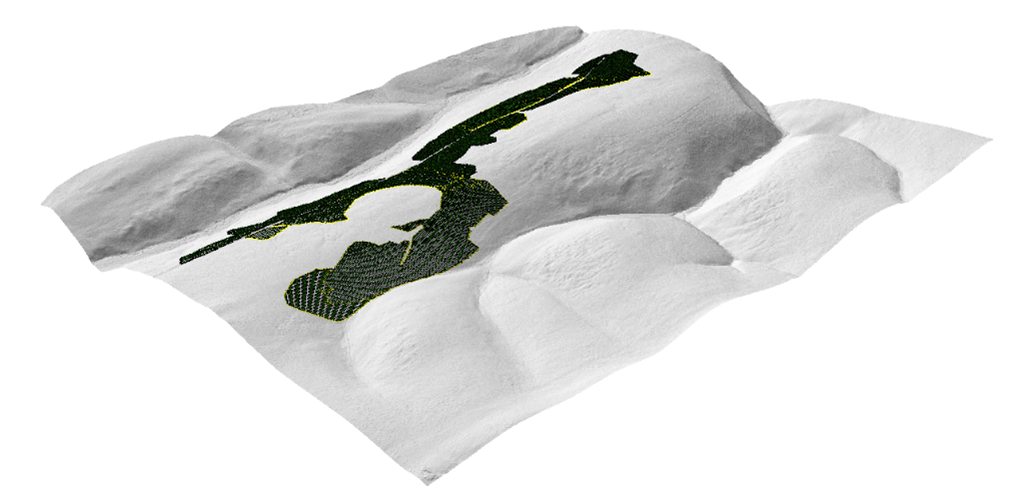
Figure 24 - Digital Planting Tool Result in 3D
Workflow B: Consider Aspect Features Only Where Slopes are Between a Specific Range.
Here we will consider the areas with moderate/steep slopes the same as we did in the previous exercise, but then we will set the orientation of the rows on flatter terrain separately.
- Open Workflow B – Step 3.terx, or continue with the files from the previous step associated with workflow B.
Select Aspect Polygons
- Use Select Feature by Layer.
- Choose the Feature Aspect Ranges layer.
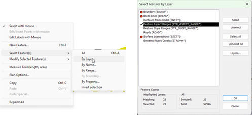
Figure 25 - Selecting Aspect Polygons
- Click OK (you’ll see how many aspect polygons were selected).
Open the Digital Planting Tool
- On the Optimization Toolbar, select Digital Planting.

Figure 26 - Digital Planting Tool is located in the Optimization Ribbon
- Configure Planting Parameters:
- Row Spacing: 4 m
- Point Spacing (within row): 2 m
- Minimum Trees per Row: 1
- Orientation: Leave as Auto to orient by terrain aspect
- Symbol: Choose a tree symbol (e.g., pine)
- Note: Optionally, you can enable Connect points along row to form polyline between points.
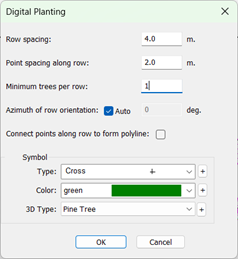
Figure 27 - Digital Planting Tool Configuration
- Click OK to run the tool.
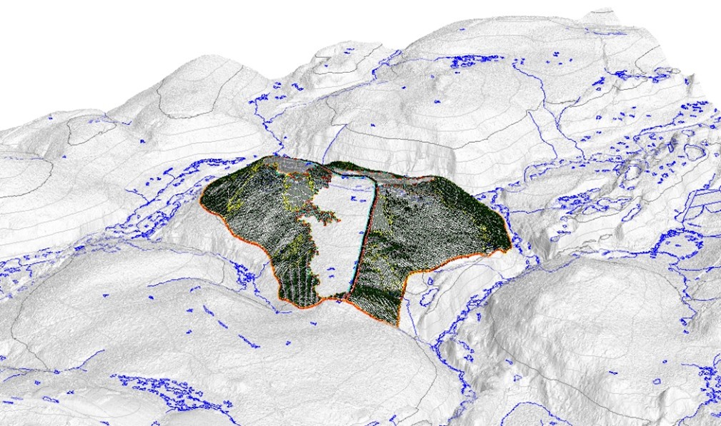
Figure 28 - Digital Planting Tool Result in 3D
Next, we are going to set the orientation for the 3 polygons that represent flat areas. We’ll start with the large southern most slope polygon that represents slopes less than 7%.
- Examine the area and note this portion of the block is relatively flat and adjacent to the main block road on the east side of the polygon. Recognize that, regardless of the aspect of the terrain in this area, we would like a relatively direct route for machines to travel to the road.
- To determine a reasonable direction to orient the rows, use the measure tool to calculate the desirable aspect.
- In the plan view, right click, select Measure Tool
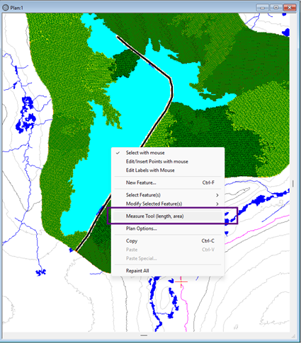
Figure 29 – Select Measure Tool
- Click to draw a single line across the polygon of interest in the direction you would like rows to be oriented. Note the measurement reported as a bearing.
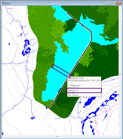
Figure 30 – Bearing being reported with the measure tool
- Right click in the Plan view and toggle off the measure tool.
- Select the polygon of interest (southern most cyan polygon).
Open the Digital Planting Tool
- On the Optimization Toolbar, select Digital Planting.

Figure 31 - Digital Planting Tool is located in the Optimization Ribbon
- Configure Planting Parameters:
- Row Spacing: 4 m
- Point Spacing (within row): 2 m
- Minimum Trees per Row: 1
- Orientation: Turn Auto off and set the orientation as 121°
- Symbol: Choose a tree symbol (e.g., pine)
Note: Optionally, you can enable Connect points along row to form polyline between points.
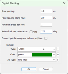
Figure 32 - Digital Planting Tool Configuration
- Click OK to run the tool.
For the remaining 2 polygons that represent flat areas, we’ll note that the terrain is flat, but the road is near the top of the hill. Rather than manually setting the orientation of these polygons, we can still use the “auto” function for both features to give desirable results.
- With the mouse, using a left click, and holding the shift key, select both the northern cyan polygons.
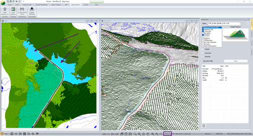
Figure 33 – When two features are selected, note the number of features selected reported in the bar at the bottom, and selected features show a cyan cross hatch.
- Open the Digital Planting Tool and run it with the same settings as last time but change orientation back to “Auto”. Press OK.
- Review results.