Step 2 - Create Polygons Based on Surface Attributes
Updated April 16, 2026
This article applies to:
- Terrain Forestry
- RoadEng Forestry
The Digital Pre-Planting Tool can be run on any polygon feature(s). However, since its intended use is to create rows and points oriented with the slope of the ground to better support mechanized operations, it is generally preferable to create polygons that partition surfaces within the block boundary based on surface aspect. These features can then be used to automatically orient rows and points.
For blocks dominated by moderate slopes, simply polygonizing the surface aspect may be sufficient to achieve desirable results. This is workflow A below.
For blocks with a significant portion of flat areas or regions with excessively steep (inoperable) slopes, users may first wish to isolate areas outside of flat and inoperably steep zones within the block. They can then run the Polygonize by Aspect tool on slope features within the desired slope range. This is workflow B below.
Regardless of the workflow being implemented, the Polygonise tool’s user interface and functionality remain consistent.
- Calculate Polygons Within – This section of the dialog allows the user to limit the extent of the surface where the tool is applied. It can be run:
- On the Entire TIN Surface, or
- Within selected feature(s). The Auto option automatically populates the feature list with currently selected features, while the Feature (s) option allows the user to manually choose features by name.
- Exclude Overlap With – This section allows the user to exclude specific areas from the polygonization calculation. For this, the user can manually choose features by name.
- Generate Features by Attribute/Range – This section allows the user to select which attribute to use for polygon creation:
- Elevation.
- Slope (In degrees or slope percentages), or
- Aspect
The user would like to create polygons from and allows them to specify the range of values that would be grouped into single features.
The tool also includes functionality to specify:
- Grid Approximation Cell Size – Most tools and functionality in the Terrain Module consider the surface as a TIN. The Polygonize tool does not, instead it uses a raster, and the cell size controls the size of each cell. When selecting a reasonable cell size, the user should be cognizant that large cell sizes tend to hide details visible in the original TIN surface, but small cell sizes can increase calculation time and produce results that are too detailed for their intended purpose.
- Minimum Feature Area – Often when polygonizing features outputs that include very small polygons can be considered undesirable. To help mitigate this, there is an option to specify a minimum output feature size. This functionality limits the output feature size, but when doing so, it merges small polygons that would have been encompassed by separate attribute ranges into larger features. Determining the best minimum feature area for a project can be subjective and the user may find achieving the most desirable results for what “look’s right” may require some review and iterating.
The image below illustrates where these options in the user interface are.
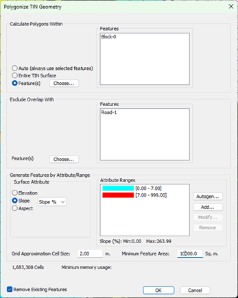
Figure 10 – Polygonize Tool Dialogue.
Workflow A: Only Consider Aspect
- Continuing from the previous step, or by opening the file Workflow A-Step 2.terx, ensure the polygons representing the Harvest Block features are selected.
- Go to the Feature Tools ribbon → Polygonize.
- Confirm your features are selected (they will appear in the feature list).
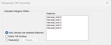
Figure 11 - Polygonize - Selecting Features
- Under Surface Attribute, choose Aspect.
- Click Autogen to define auto generate the intervals. You can adjust the number of intervals and colouring. We selected 8. Press OK.
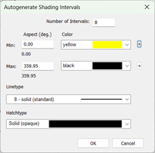
Figure 12 - Polygonize - Auto Generation of Intervals for the Polygons – by Aspect.
- Adjust the grid approximation cell size to be 4m and the minimum feature area to be 3000 sq.m.
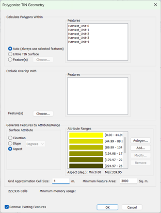
Figure 13 - Polygonize Dialogue Completed – by Aspect.
- Click OK to generate aspect-based polygons.
The results should appear similar to the results below.
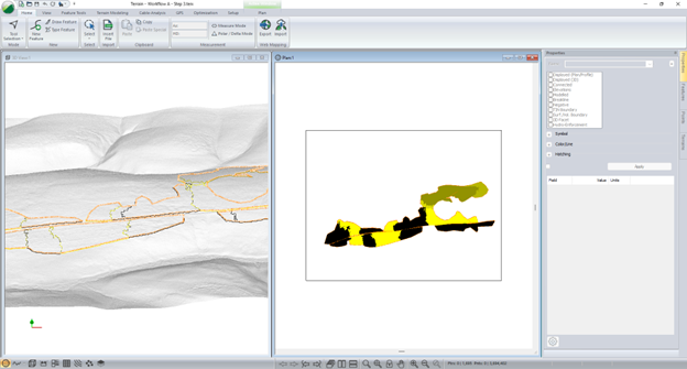
Figure 14 – Polygons created by Aspect.
Workflow B: Consider Aspect Features Only Where Slopes are Between a Specific Range.
The previous example was dominated by moderate slopes, and therefor the aspect of said slopes would heavily influence the directions machines should travel on them. On some projects, this may not be the case, and you may want to only create aspect polygons where there is enough slope to influence machine travel directions.
To illustrate this, we’ll use another example:
- Open Workflow B – Step 2.terx, note the work associated with step 1 has already been completed for this file.
- Activate the 3D view to familiarize yourself with the topography.
- To make the topography more obvious, apply vertical exaggeration of a factor of 5.
- Right Click in the 3D View→ 3D options.
- Change the vertical exaggeration from 1 to 5 by right-clicking on 3D Window – 3D Options…,as shown below.
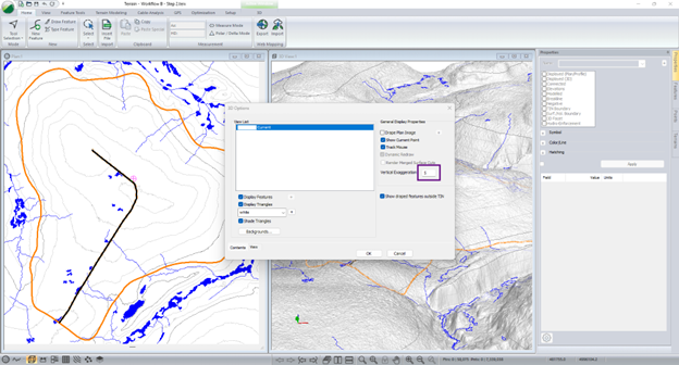
Figure 15 – Exaggerate vertical in the 3D to make topography more obvious.
- Click the harvest_unit feature (orange) to select it in the plan view. When selected it will turn magenta.
- Go to the Feature Tools ribbon → Polygonize.
- Confirm your block features are selected (they will appear in the feature list).
- To prevent Polygons from being created on the roadway, add Road_RoW-0 to the Exclude Overlap With portion of the dialogue.
- Under Surface Attribute, choose Slope.
- Use the drop-down list to select Slope %.
Rather than calculating ranges at equal interval (as we did with autogen and aspect previously), we want to create two attribute ranges at specific values to create slope features.
- To assign the two attribute ranges we’d like to assign, press Add….
- In the dialogue that appears, set the min value as 0, the max value as 7, and the color as Cyan. Press OK.
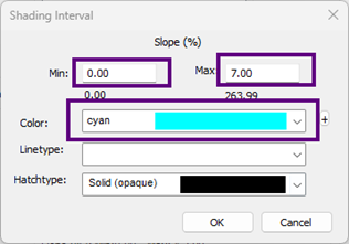
Figure 16 – Setting shading interval for a specific range and color.
- Press Add… again, to create an additional slope range to create polygons. In the dialogue that appears, set the min value as 7, the max value as 999, and the color as Red. Press Okay.
- Set the cell size to 2, and the minimum feature area to 10,000. Press OK.
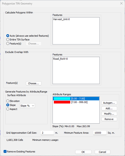
Figure 17 – Polygonize tool set to produce slope features.
The results should appear similar to the solution illustrated below.
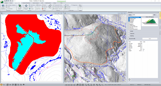
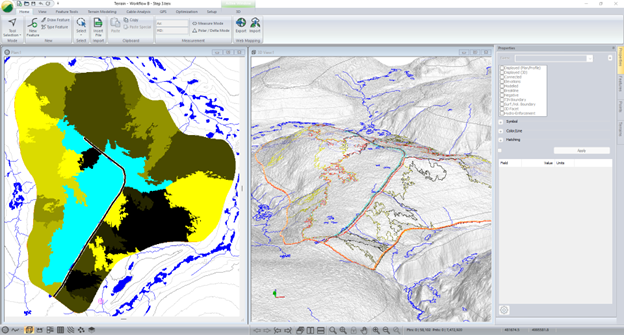
Figure 18 – Polygons created to represent slopes over 7% (red) and below 7% (cyan).
The user should recognize that flat areas are shaded by cyan colored polygons, and steeper areas are shaded red. In flat areas, we will set row direction to traverse directly across the polygons toward the road, on the steeper areas (red) we would still like our rows to be oriented with the aspect of the terrain.
To facilitate this, we will polygonize aspect features within the steep slope polygon (Red).
- Select the large red polygon that occupies the majority of the area within the block boundary. The feature should appear similar to the image below when selected and the number of features selected should be 1.
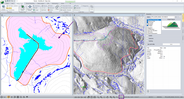
Figure 19 – Feature selected for slopes over 7%.
- Go to the Feature Tools ribbon → Polygonize.
- Confirm your Slope Feature is selected (they will appear in the feature list).
- To prevent Polygons from being created on the roadway, and Road_RoW-0 to Exclude Overlap With portion of the dialogue.
- Under Surface Attribute, choose Aspect.
- Click Autogen to define auto generate intervals. You can adjust the number of intervals and colouring. We selected 8. Press OK.
- Adjust the grid approximation cell size to be 2m and the minimum feature area to be 3000 sq.m.
- Click OK to generate aspect-based polygons.
We now have two different types of polygons that were generated from the topo surface, the slope features, within the block boundary, and the aspect features where our slope exceeded 7%. The results should appear similar to below.