Additional Resources
Updated April 16, 2026
This article applies to:
- Terrain Forestry
- RoadEng Forestry
Test and Improve Results
The outputs of this tool are highly dependent on the selected parameters and the underlying topographic variability. Choices such as surface attribute classification, grid approximation cell size, and minimum feature area can significantly influence intermediate processing and may introduce unintended effects in the final polygons
To test and Improve results while working with the Polygonize and Digital Pre-Planting tools, the user can run through the following verifications:
Topography:
- Ensure the DEM/LiDAR resolution is appropriate for the project scale.
- Verify that the TIN surface doesn’t contain holes.
- Check for abnormal spikes or other surface issues.
Polygons:
- Review the total number of polygons.
- Check the average polygon size.
- Identify very small or isolated polygons.
- Consider removing features or applying a higher minimum feature area value.
Typically, inconsistencies in the polygons generated, will need to be addressed at the minimum feature area or unusual (skinny) shapes.
Validate Tree Generation Results
We recommend evaluating the geometry derived during intermediate steps and adjusting/revising settings to favour a solution the user considers desirable.
After generating tree features:
- Confirm that spacing aligns with slope and suitability.
- Review the spatial distribution visually in the 3D window.
- Verify the total number of trees and confirm that the solution satisfies the desired minimum.
If results appear inconsistent:
- Rerun the tool with a different row orientation azimuth.
- Revisit the Polygonize tool:
- In flat areas:
- There may be a need to remove individual trees. You can select them manually by left-clicking their point in the Plan window or their symbol in the 3D window, then press Delete button in your keyboard.
- To review the results, zoom in to visualize the tree distribution, especially near the polygon corners.
- Other adjustments:
- Reduce number of auto intervals in the Polygonize dialog.
- Adjust grid size and minimum features area.
- In flat areas:
Apply an Iterative Test Strategy, if necessary.
Some iteration is typically required to achieve an appropriate balance between capturing terrain complexity and maintaining a simplified, usable result.
Since the Polygonize tool operates on one variable at a time (Aspect or Slope), optimization can focus on testing different interval configurations within that variable.
Select the configuration that provides the best balance between ecological realism and operational efficiency.
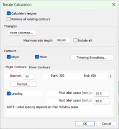
Figure 39 – Generate TIN Surface dialog.
In the Terrain Calculation dialog, you can define the maximum side length of the triangles. A rule of thumb for defining this value is: the higher the density of points or the better the resolution of the data, the lower this value can be set.
That being said, there is a point of diminishing returns where a very low value can create surfaces with holes.
You can confirm whether holes were created by reviewing the surface in the 3D window. If this occurs, regenerate the TIN surface with a higher maximum side length value.
The Contours Range controls the creation of polylines that define the elevation of the terrain based on a user-defined interval.
Connect Tree features
The properties panel controls how a feature is displayed and interacts with the model or surface. To connect the Tree features within a single polyline, you can mark the Connected property and then press Apply button.
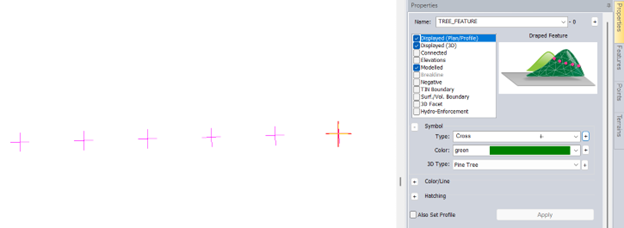
Figure 40 – Properties panel.
After enabling the Connected property and pressing Apply, the Tree feature will show up as a polyline feature.
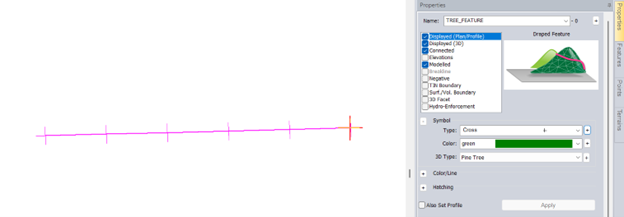
Figure 41 – Properties panel – Connected checkbox enabled.
Additional functions and concepts that may be useful include:
Understanding Feature Properties:
Points, Features, Attributes and Feature Properties.
Terrain Tools Concepts: Understanding the 3D Modelling Functions.
Feature Selection Tool:
Selecting Features
Selecting and Joining Features
Selecting Features by Properties
Selecting Features by Layer
Feature Modification:
Feature editing with mouse
Introduction to Terrain Feature Editing
Drawing Features Using the Mouse
Drawing Features Using the Mouse and Keyboard
Edit and Insert Points with Mouse
Join
HotKeys
Join two features
Join with Ctrl + J hotkey
Break
Break a Feature with Ctrl + Q hotkey
Buffer
Close
Simplify/Smooth
Terrain Modelling
Simplify Slope labels
Thinning Data & Working with Large Datasets:
Working with Large Data & Backgrounds
Thinning LiDAR Data
Thinning DEM Data
Thinning Other Data
Delete Polygonized Features
Polygons generated by the Polygonize tool can be deleted using one of the following methods:
- Layers dialog: In the Plan window, right-click and select Select Feature(s) – By Layer…- Select the polygonized features by double-left clicking or pressing the Select button. Then, press Delete on the keyboard.
- Select by name dialog: In the Plan window, right-click and select Select Feature(s) – By Name…- Look for the polygonized features and press Select. Alternatively, press Advanced… and type the name of the feature. Once the features are selected, press Delete on the keyboard.
- Delete button: In Terrain Modeling ribbon, select Delete button.
This will open the Delete Terrain Model / Features dialog shown below:
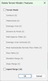
Figure 42 – Delete Terrain / Features dialog.
Enable the Aspect/Slope range checkbox and press OK.
This will remove those features from the model.