Back to Terrain Module
Note: This example includes 3.6 million elevation points and easily builds the TIN on import. Building the TIN surface on import for large files may lead to a considerable impact on computer performance and computation time.
Step 1 - Data Import & Terrain Modeling
Updated April 16, 2026
This article applies to:
- Terrain Forestry
- RoadEng Forestry
As noted above, the tool is primarily intended to generate features that are dependent on the geometry of the topographic surface they contain. To facilitate this, our first step is to input the spatial data we would like to consider (block boundary and topographic surface information and model our topo surface as a TIN.
- Open RoadEng Terrain (or Terrain Tools) Version 12.
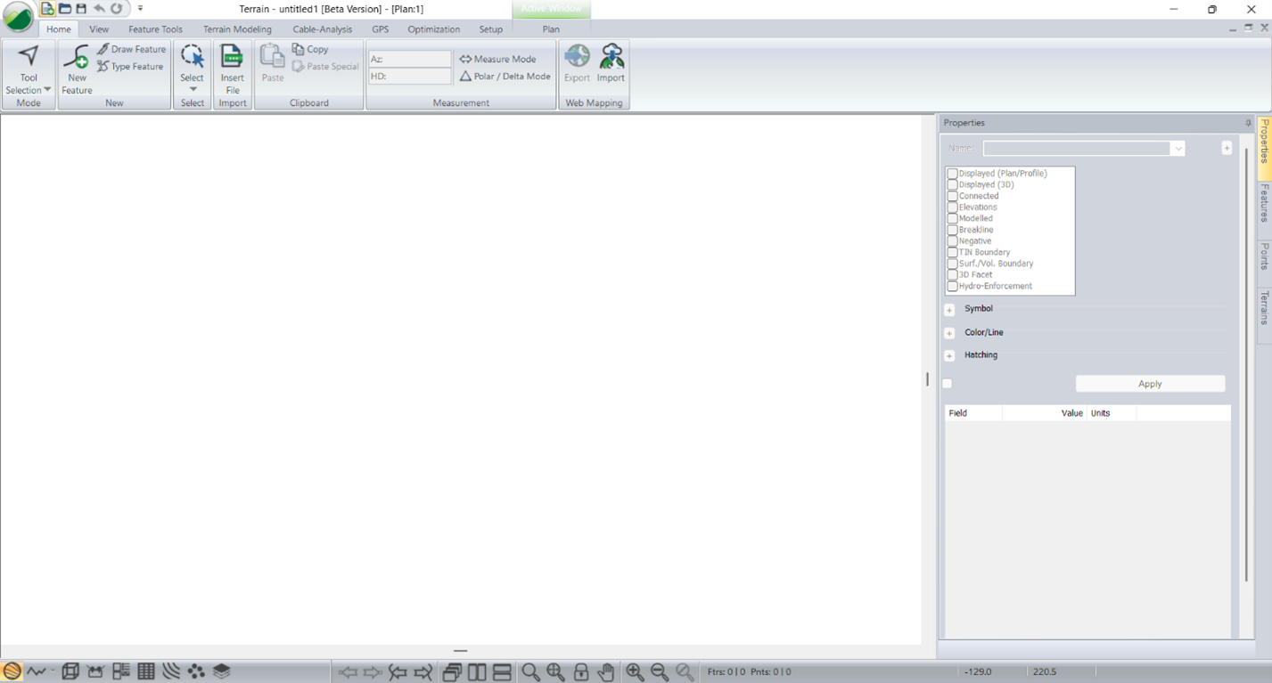
- You’ll start with a blank plan window — no data yet.
Figure 2 - Blank Terrain when opened
Import DEM (Digital Elevation Model)
- Open your folder containing your planting data.
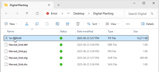
Figure 3 - Typical Data Needs - Topo & Block Boundaries
- Drag and drop your topo data directly into the plan window. We will be using a 1m DEM geotif.
- In the Select Option dialog:
- Select Raster DEM, (note: this is not an image file – but you will have that option presented to you). Press OK.
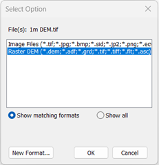
Figure 4 - DEM Import Selection
- In the Import Options dialog:
- Uncheck Display Points.
- Check Display Extents Border and Create 3D Model.
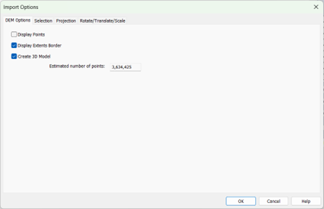
Figure 5 - Import Options Dialogue for DEM Data
- On the projection tab, confirm or set the projection (most GeoTIFFs will include this).
- Click OK.
Note: This example includes 3.6 million elevation points and easily builds the TIN on import. Building the TIN surface on import for large files may lead to a considerable impact on computer performance and computation time.
If importing large amounts of topo data, the user may see a warning like the one below,
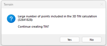
Figure 6 – Large number of points in 3D TIN Calculation warning.
It’s worth noting there is a practical limit to how large, modelled datasets are. Conservatively, Softree recommends users try to keep the number of modelled points to be less than 10 million. If the imported dataset exceeds 10 million points the user should consider thinning the data or isolating its extents to a filtering region/area of interest.
View the Surface
- Click outside the selected points to deselect. (they import and are shown in magenta initially)
- Use the Zoom to Extents tool to center your data.
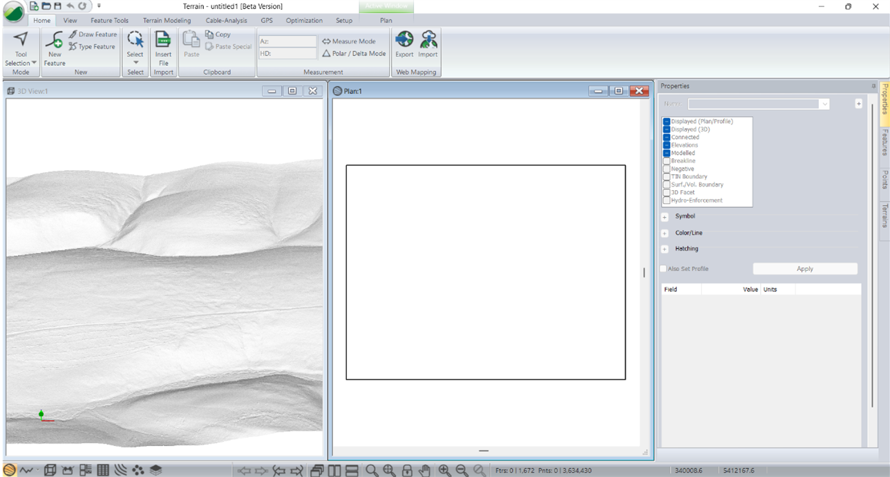
- You can also press the 3D window button to view your data
- Press Tile Vertically button to align the Plan and 3D window.
Figure 7 - Modelled 3D Surface
Import Harvest Unit Boundaries
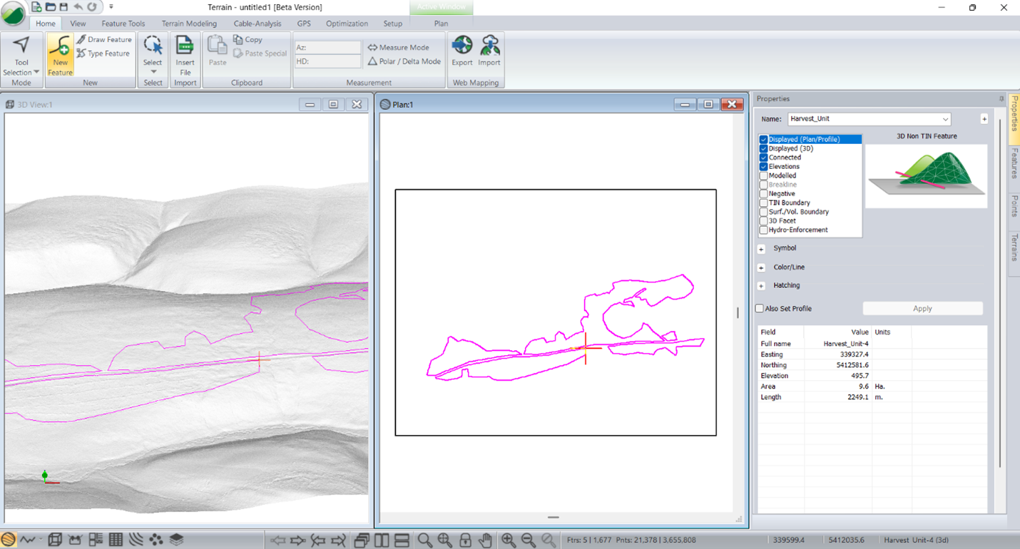
- Drag and drop your Shapefile containing block/harvest units.
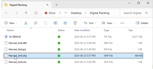
Figure 8 - Shape File & Companion Files for it
- Accept default options (projection is built in). Press OK
- These units will be used to determine planting areas.