Creating a Multi-Span Setup
Updated September 22, 2023
This article applies to:
- Terrain Forestry
- RoadEng Forestry
Link to the file discussed in this tutorial: Cables Multi-Span.terx
This example was done and written for Version 10:
For some terrain, cable yarding with intermediate supports is the best solution. The Cable Analysis module does not handle such multi-span setups directly. However, this example will show you how to approximate a multi-span setup.
We will create two single span setups on the same profile and display them together.
1. File | Open
This file contains a single profile feature (dline6-0) created from a traverse.
First, create a setup to represent the first segment of the multi-span.
2. Select menu Cable Analysis | Assign Setup to open the D-Line Assign Setup dialogue box shown below.

Figure 1: D-Line Assign setup dialogue box, first leg.
3. Change the setup data to match the figure above.
- To select the Shotgun setup, highlight Shotgun, and then press the Select button (or double click on).
- Leave the default Head Spar location (at the start of the profile).
- Set the Tail Spar Station to 100.0 and Height to 20.
- Press OK.
4. Set up a particular analysis (this is unimportant – you can choose a different one if you like):
- Select menu Cable Analysis | Edit | Calculation Parameters.
- Change the Type of Analysis to Minimum deflection given load.
- Set the load to 30000.0.
- Press OK twice.
Your Profile with analysis should appear similar to the figure below.
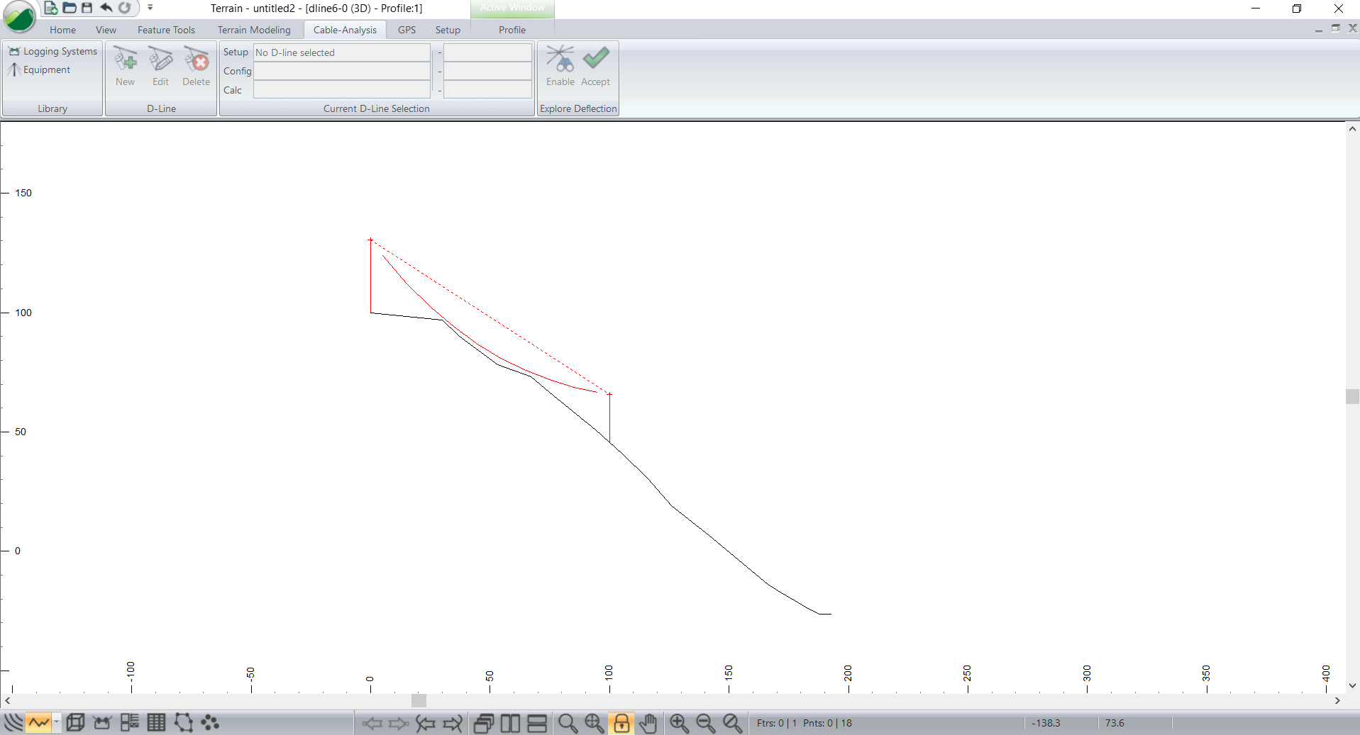
Figure 2: The first leg of the multi-span system.
The Cable Analysis software only allows one setup per profile feature. To create the second half of our multi-span system, we will create a duplicate of the current profile feature.
5. Duplicate the dline6-0 feature:
- If this feature is not selected (magenta), select it now.
- Feature Tools | Duplicate or type
.
The new feature (dline6-1) comes up in Move/Size mode; be careful not to move it with the mouse. Now create a new Profile window to view the new (selected) feature.
6. View |Window | New Window | Profile.
7. To view both windows, choose menu Window | Tile Vertically.
8. Click in the left Profile window to de-select the new feature (and to exit Move/Size mode).
9. Zoom, pan or scroll so you can see the features as below.

Figure 3: Two identical features viewed in two Profile windows.
Notice that the new Profile window (left) already contains a yarding setup identical to the one we created earlier; when you duplicated the feature, you also duplicated the Cable Analysis information (attribute) attached to the feature.
Now let’s setup the second leg of our system.
10. Select window Profile:2, and then choose menu Cable Analysis | Edit.

Figure 4: D-Line Assign setup dialogue box, second leg.
11. Change the dialogue box to resemble the figure above. Double click on the sub-view (or right click and choose Profile:2 Sub-View Options).
- Set the Station for the Head Spar to be the same as that for the previous Tail Spar (100.0); this is your intermediate support.
- Set Cut Depth to 10.5; this effectively shortens the tower to 20m.
- Set the Tail Spar to be at Station 9999 (the end of the feature) and Height 0.0.
- Press OK when done.
Now we have the two halves of our system:

Figure 5: Two parts of the multi-span systems shown independently.
Now we will overlay the two profiles in a Multi-Plot window.
12. Make sure that the two profiles have the same scale (use the Scale toolbar or the Profile window options).
13. Select menu Window | New Window | Multi-Plot.
An empty Multi-Plot Window will appear.
14. Create a Sub-View for each of the two Profiles:
- a.Right click | New Sub-View | Profile:1.
- b.Right click | New Sub-View | Profile:2.
By default the two windows are aligned but the profiles probably don’t line up.
15.Set scroll position for Multi-Plot Sub-View Profile:2:
- Clear the Auto check box in Scroll Position.
- Set the Station to -50.0.
- Set the Elevation to 50.0.
- Press OK.

Figure 6: Profile Sub-View options
16.Set the same scroll position for Multi-Plot Sub-View Profile:1:
- Select menu Edit | Shuffle Front to Back
to bring Profile:1 to the front. - Repeat the steps above to open the Sub-View options dialogue box and set the Scroll Position.
17. If necessary, use the mouse to adjust the position of the two profile sub-views so they are:
- Arranged nicely on your Multi-Plot page
- Occupying the same rectangle (figure below).
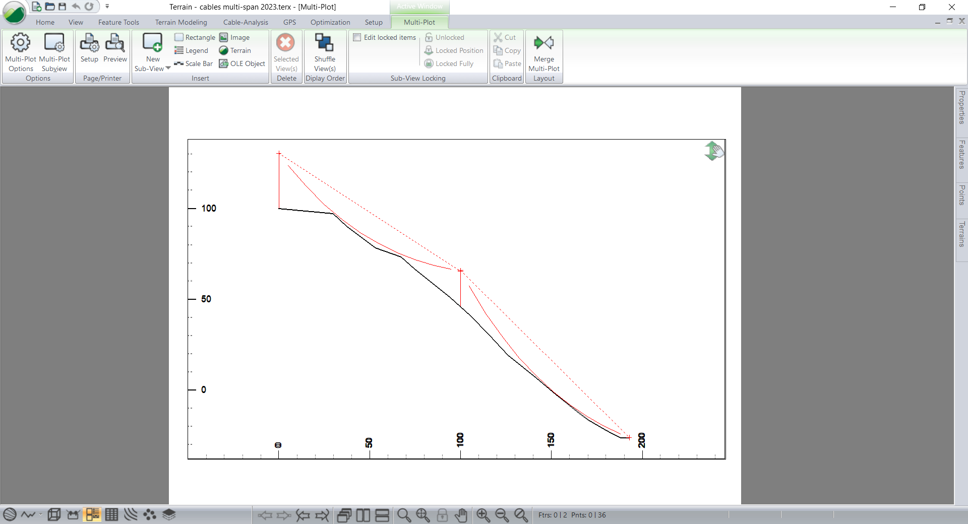
Figure 7: Multi-Plot of a multi-span skyline.
Now the two separate setups appear as one multi-span as shown above. The calculations are still based on two separate systems and do not incorporate the physics of a linked system; this is not important for the simple third points calculation and is an approximation for other calculations.
At this point you may want to adjust the position of the two Profile Sub-Views and add other information to the output sheet. Note that the Grid has been enabled (menu View | Multi-Plot Options) so that it is easy to get the windows aligned.
18. File | New. Do not save changes.