Cable Planning using a TIN
Updated August 14, 2020
This article applies to:
- Terrain Forestry
- RoadEng Forestry
Download the files for this example here: Cable Planning Using a TIN.zip
This example will demonstrate how to do setup profiles for cable analysis based on a TIN model.
The TIN model used was created from a LiDAR data set (trimmed down to keep the example size small). It is assumed that the reader is familiar with both TIN modelling and cable analysis. This example will explain how to combine the two.
1. Open the Terrain module and choose menu File | Open.
2. When prompted, open the original ground terrain Topo.ter (included with example).
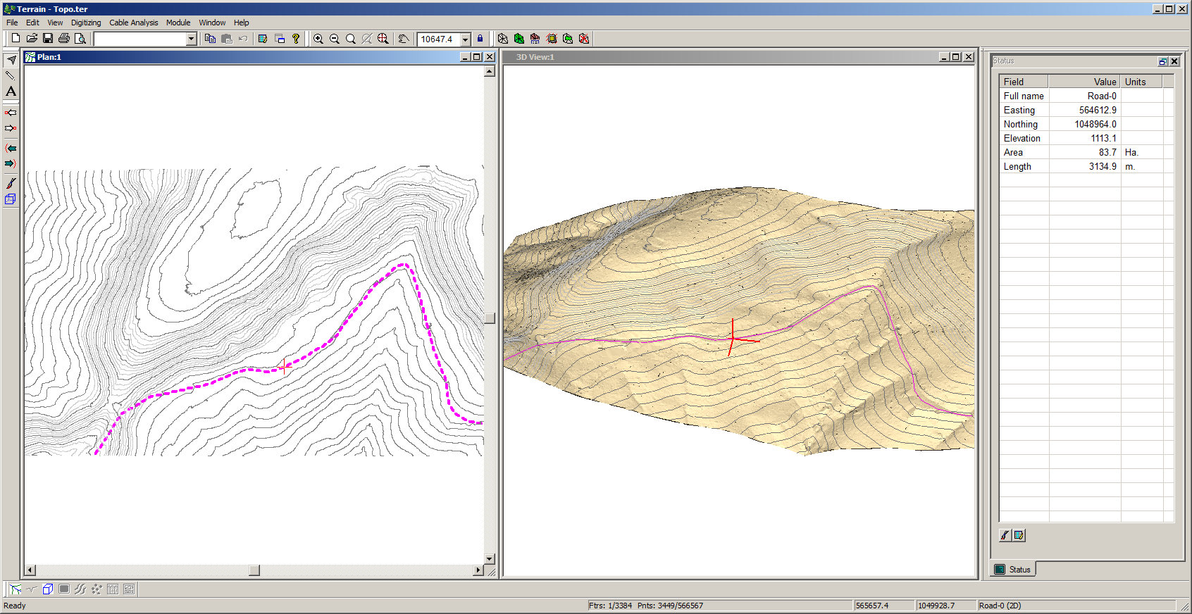
Figure 1: Topo.ter
Note: Topo.ter has a TIN model, contours and a road centerline feature. We will add a cable logging profile.
3. Choose menu Edit | New Feature. Set the feature properties as shown in Figure 2 below and press Mouse.

Figure 2: Feature properties dialog
Note: When Elevations is Off and Modelled is On, the feature is 'draped' over the TIN model.4. In the Plan window draw a feature perpendicular to the road, similar to the one shown in Figure 3 below.

Figure 3: Profile Feature in Drawn in the Plan Window
5. Choose Window | New Window | Graphics | Profile.
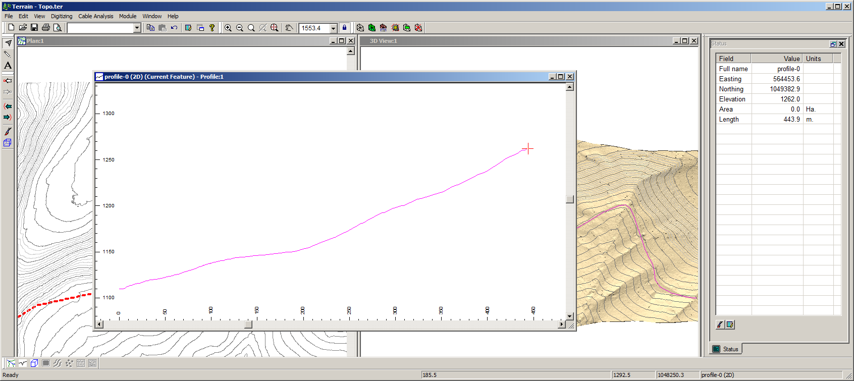
Figure 4: Profile from a Draped Feature
Note: The Window | New Window | Profile menu creates a profile of the currently selected feature.We will now assign a cable system to the profile.
6. Choose Cable Analysis | Assign Setup and set the parameters as shown in Figure 5 below. Press OK.

Figure 5: D-line Setup Dialog
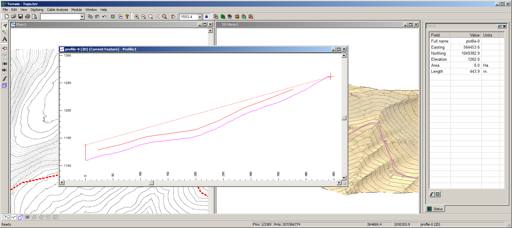
Figure 6: D-line On the Profile
7. In the Plan Window click on the end point of the new profile and rotate it as shown in Figure 7.
Note: The Profile window updates to reflect the new ground position.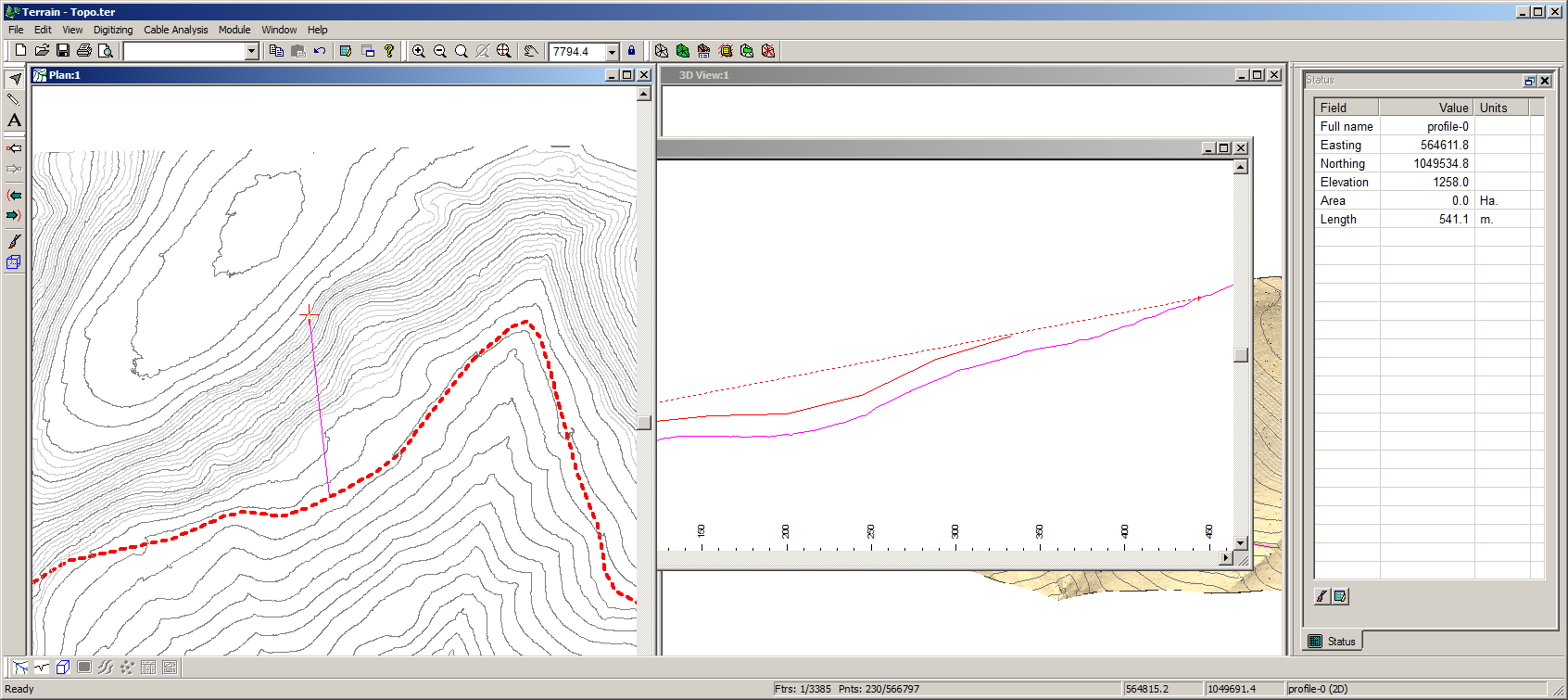
Figure 7: Rotated Profile
8. With the Profile Feature still selected ,choose menu Edit | Modified Selected Feature | Duplicate.
A new feature will be created with a move/size box around it.
9. Move the new feature to a location similar to that shown in Figure 8.

Figure 8: Second Profile Feature.
10. Choose Window | New Window | Graphics | Profile.
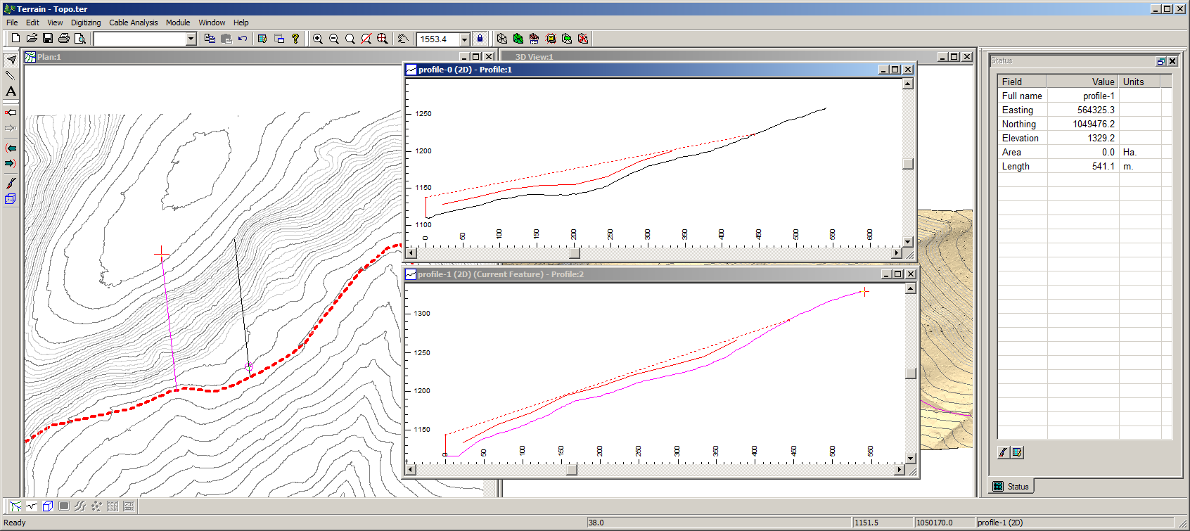
Figure 9: Second Cable Profile Window.
Note: When we Duplicated the feature, the Cable Setup information was also duplicated. Thus is it easy possible to create a series of cable profiles.11. This completes our example. Choose File | Exit. Do not save the changes.