Transit Survey
Updated July 08, 2021
This article applies to:
- Terrain 3D
- Terrain Forestry
- RoadEng Civil
- RoadEng Forestry
This Knowledge Base article is an excerpt from one of our tutorial files. The files referenced in the article, as well as the full tutorial document, are available in our Tutorial Installer.
Transit surveys are conducted by taking an initial backshot, and a series of foreshots that are calculated using turning angles. The horizontal angle is measured by turning right (clockwise) from the backshot to the foreshot.
Note: See Getting Started section for file install folders (<SurveyMap> and <Defaults and Layouts>)
 File |New, select Traverse Document. Press OK to create a new traverse.
The Starting Coordinate dialogue box below will open with default values (0.0, 0.0, 100.0).

Figure 1: Starting Coordinate Dialogue Box after Setting Initial Position.
- Set the coordinates as shown above: type 2900.0 for Easting (X), 1600.0 for Northing (Y) and 200.0 for Elevation (Z). Press OK.
The notes entry table is now set up according to the contents of your default screen layout (Normal.slt). We need to change to accommodate theodolite data.
- View | Retrieve Screen Layout, select <Defaults and Layouts >\Training\training transit.slt.
- Double click in any gray area to access the Traverse Entry Options
- Dialogue box (this is also available from the right click context menu). The screen layout training transit.slt has been configured for entry of Azimuth in Deg:Mins:Secs (0 to 360), and Slope in Zenith deg:min:sec (0 to 180) angle. Press the Options… button; note that the horizontal angles will be calculated using turning angles. Press Cancel, and Cancel again, to return to main screen.
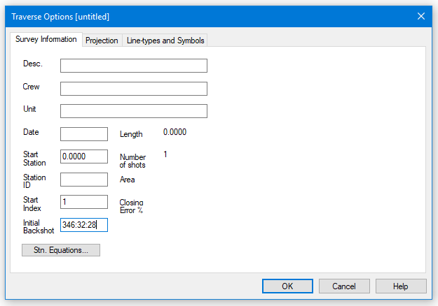
- Right click in any gray area on the Traverse screen; select Traverse Options… (at the bottom of the context menu) to open the dialogue box shown below (or you can select Traverse | Traverse Options from the main menu). Select the Survey Information tab.

Figure 2: Survey Information Dialogue Box
- Type in the Initial Backshot 346:32:28 as shown above.
- Click on the Projection tab and change Units to Imperial (ft.) (if necessary). Press OK.
- Place the cursor in the Label column at Station 0.00. Type in BM (short for bench mark) as the first label. Press <Enter>.
- Refer to the Theodolite Survey notes in the figure below. In the Fore Right field (HORZ ∠) for Pt # 2 type 106.4409. Press <Enter>.
An error prompt appears, stating “Invalid value (minutes and seconds must be from 0 to 60)”. The format used in the paper notes (ddd.mmss) is not supported.
- Press OK to close the message box.
- Type 106.44.09 instead. Press <Enter>.
Note: Type all Horizontal angles (Fore Right) and Vertical angles (Zenith) as deg.min.sec or deg:min:sec, for example 106.44.09 or 106:44:09 not 106.4409.
With the exception of labels, the notes can be entered using the number pad only. Use decimal point delimited fields for ease of entry. The values will be displayed with the colon delimiter.
- In S.D. (Foresight slope distance) type 137.33. Press <Enter>.
- For Zenith (VERT ∠) type 89.12.20. (See Note above) Press <Enter>.
- Type in the Inst. Height (HI) of 5.2. Press <Enter>.
- Type in the Target Height (Rod Ht.) of 5.2. Press <Enter>.
Notice that the instrument and target heights have been copied into the next record. Any changes can be typed in, otherwise <Enter> will accept the previous value.
- Enter the remaining notes from the figure below, continuing from PT # 3.

Figure 3: Theodolite Survey Notes
- Optional: If you did not complete the notes entry, open <SurveyMap>\Other\transit.tr1 and skip the following step.
 File | Save. Save as <SurveyMap>\Other\transit2.tr1.
This traverse represents a closed polygon. However, due to an imperfect survey, the end point is not coincident with the start.
- Traverse | Close Traverse Coordinates. Press OK to confirm closing of traverse. A Coordinate Adjust Log appears reporting a closure error and area of closed traverse. Press OK.
Notice that an asterisk, *, appears next to the final station to indicate that it is an absolute station (coordinates are set to match the start).
- Double click on any of the stations in the station column to open the Survey Information dialogue box (figure below). Closure error is 0.002%, Area 16.73 Acres, and the length of the traverse is 3968.0391 meters. Press OK.

Figure 4: Survey Information Dialogue Box
- Select Traverse | Quick Map button. Create to open a map of the current Traverse.
- View | Retrieve Screen Layout, select <Defaults and Layouts>\Training\training transit.mlt.
- Arrange windows side by side with menu View | Tile Vertically.
The screen should now appear as shown in the figure below.

Figure 5: Final Closed Block Boundary
Note: If you select a shot in the Traverse window, the Map window will indicate the selected shot with a red cross.
- Close both the Traverse and Map Documents. Do not save changes.