Overrides Creating a Turning Lane
Updated June 25, 2018
This article applies to:
- RoadEng Civil
- RoadEng Forestry
This example will demonstrate parameter overrides by creating a turning lane at an approach to an intersection.
Note: Refer to Getting Started section for file install folders (<RoadEngCivil> and <Defaults and Layouts>).
 File | Open <RoadEngCivil>\Location2\bluff_road.dsnx.
Home tab | Assign by Range | Select the Overides tab.

Figure 1: The Assign Parameters By Range with Overrides Tab Selected
In the Parameter control, choose ACP_WIDTH (left).
Click on the first entry in the override list (Station 0+00) and press the Modify… button. Turn off Use Default and set the Value to 30.0 (figure below left). Press OK.
Press Add… another Value of 30 at Station 110. Also change the Description to read “Turn lane end” (figure below right). Press OK.


Figure 2: Override Parameter Dialogue
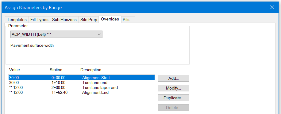
Press Duplicate… and check the Use default check box. Change the Station to 200. Change the Description to “Turn lane taper end”. Press OK. Your override list should be the same as the figure below.
Note: Without adding the taper at a specific station it will be difficult to see the transition in width of the road.

Figure 3: Override List for Turning Lane at Start of Alignment
Press OK to return to the main screen. Respond OK to “Recalculate road alignment”.
Scroll and zoom the plan window to the beginning of the design. Notice the road edges in blue now display the additional lane width.

Figure 4: Turning Lane Defined by Template Parameter Overrides.
 File | Close. Do not save changes.
Templates – Display and Reporting
Before we begin some basic concepts and definitions are required.
Surfaces
Template surfaces are used to track and report material volumes. Each template can define up to 16 surfaces plus sub-grade. Material volumes are calculated between surfaces. Thus, we can calculate and report cut and fill volumes below the sub-grade surface and up to 16 material fill volumes.

Figure 5: Template Surfaces and Enclosed Materials
Codes
Each template component has a set of pre-defined template codes. These point codes can be displayed in the Plan, Profile, Section or Data windows. In Profile and Plan the codes are connected to form linear features such as a ditch-line or sidewalk offset.

Figure 6: Template Codes