From LiDAR to Raster DEM
Updated June 11, 2026
This article applies to:
- Terrain 3D
- Terrain Forestry
- RoadEng Civil
- RoadEng Forestry
From LiDAR to DEM
This tutorial covers how to use RoadEng to convert LiDAR survey data into DEM raster in RoadEng Version 11. The tool streamlines importing and exporting worflows using LiDAR survey data, and it consists of four main steps:
- Data Import
- Data Thinning
- Terrain Modeling
- Export to DEM
Step 1: Data Import
- Open RoadEng Terrain (or Terrain Tools) Version 1.
- You’ll start with a blank plan window — no data yet.
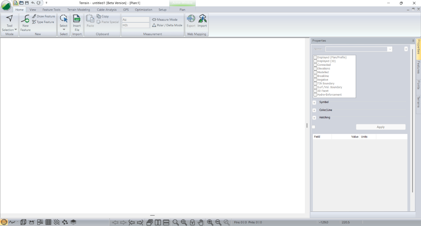
Figure 1 - Blank Terrain when opened
Import LAS (Light Detection and Ranging)
- Open your folder containing your LiDAR data.
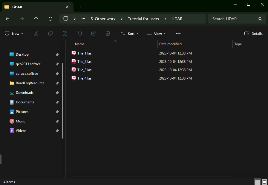
Figure 2 – LiDAR las file.
- Drag and drop your topo data directly into the plan window. We will be using a 28 million points LiDAR las file.
- In the Select Option dialog:
- Note the number of points: 2.559.203 points
- The drop-down list is already selecting 2: Ground class.
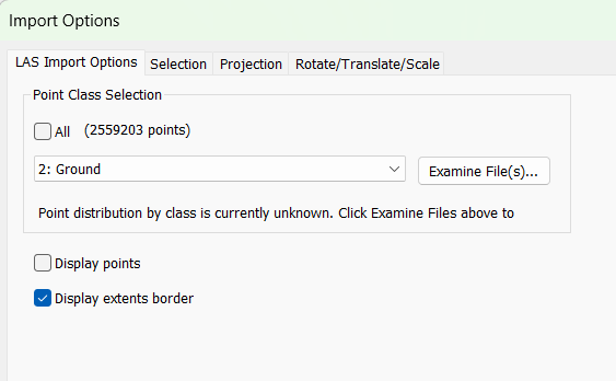
Figure 3 - LiDAR Import Options dialog.
- In the Import Options dialog:
- Press the Projection tab.
- Use the To Projection tab drop-down lists to set UTM – Universal Transverse Mercator NAD83 Zone 20N.
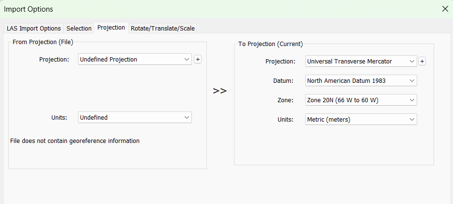
Figure 4 – Projection tab in Import Options Dialogue for LiDAR Data
-
- Note: Usually, LiDAR files already have projection settings. (In that case, you can skip this step).
- Accept any warning that may prompt.
- Click OK.
Note: This example only contains 2.5 million points. However, RoadEng handles up to 10 million comfortably.
Step 2: Thinning Data
- Select Terrain Modeling ribbon.
- Open the Simplify tool.

Figure 5 – Terrain Modeling ribbon – Simplify tool.
Set the Spacing Grid
- Set the Spacing grid to 1.5m
- Press Calculate button.
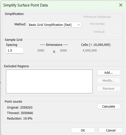
Figure 6 – Simplify Surface Point Data dialog.
-
- Note: The points will be reduced from 2.559.203 points to 2.050.666 points
- Accept any warning that may prompt.
- Press OK
Step 3: Terrain Modeling
Use the Generate Tool
- In the same Terrain Modeling ribbon → Generate.
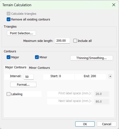
Figure 7 – Terrain Calculation dialog.
-
- Note: Contours checkboxes are already enabled.
- Press OK to calculate the TIN Surface and contour lines at the same time.
- In the navigation bar, press the Zoom to Extents tool
 .
. - Press the 3D Window
 button. This will open the 3D view.
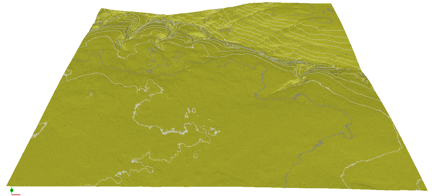
Figure 8 – Tin Surface shown in 3D Window.
Step 4: Export the Surface to DEM
Select the File button
- Choose Save As.
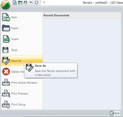
Figure 9 – File I Save As
Terrain model save name dialog.
- Type the desired
- Use the Save as Type drop-down list to select Raster DEM (.tif).
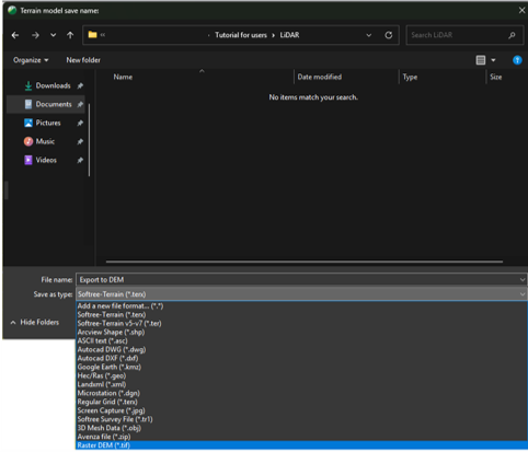
Figure 10 – Terrain Model Save Name dialog.
Set the DEM export parameters:
· Set the Cell Size Spacing (X and Y) to = 1 m.
· Ensure the Surface drop-down list is set to Surface A.
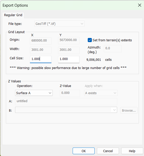
Figure 11 – DEM Raster Export Options dialog.
· Note: The cell size setting impacts the quality of the exported data. The smaller the cell size value, the better the resulting surface resolution. However, there is a point of diminishing returns, as smaller cell sizes significantly increase the number of grid cells and can negatively affect export performance.
· Click OK to export the file.
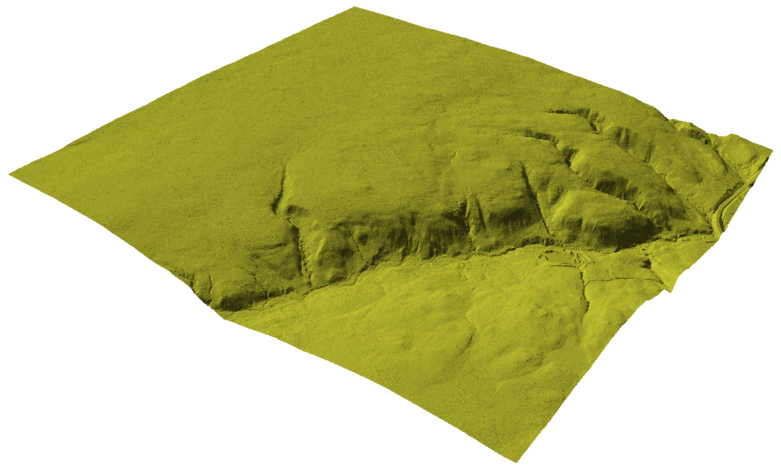
Figure 12 – DEM file re-imported into Terrain Module - Result in 3D