Path Explorer common workflow
Updated May 03, 2024
This article applies to:
- Softree Optimal
Path Explorer AI is an ideal starting point for a preliminary road project where you'll explore rapidly feasible road locations between point A & B. These routes are optimized minimizing earthworks and surfacing costs while meeting constrains like max or min grade, side slope, max cut/fill, no-go zones, high-cost zones, among others.
In the text below, you'll find a common workflow:
STEP 1 - Create a Terrain Model
Path Explorer AI works on a valid terrain surface.
- First, open Terrain Module and import your topo data. (see Digital Terrain Modelling for more info).
- Then, select Terrain Modeling ribbon I Generate TIN.
- This will open the dialog box below:

Figure 1: Terrain Calculation dialog.
- Ensure a Terrain Surface is Calculated.
STEP 2 - Creating a A - B feature
When looking to find the optimized path to connect A - B points, you'll need to create or set a feature to link those points. The user may prefer creating a straight line from A to B or simply using an existing preliminary road center line feature to run the calculation. It really doesn't matter the route this feature takes, Path Explorer only considers the Start and the End point for looking for feasible paths based on established parameters and restrictions.
Method 1) - Using existing points (Join them):
When your points cloud has been imported, you can join them to create a feature from A to B.
Right-click on Plan Window and Select Feature(s) I By Name...

Figure 2: Select Feature(s) By Name.
You will be prompted with a dialog similar to Figure below.
Figure 3: Select Features(s) by name dialog.
Select all points and press OK. Please note that your points will be highlighted in magenta.
Press the Feature Tools ribbon and press Join (or use the keyboard Ctrl+J), as shown below:

Figure 4: Join Selected Points.
Your result will be similar to below:
Figure 5: Joined Feature.
Method 2) - Draw a feature:
If you don't have a feature from A to B, you can simply draw it.
Press Right-click on Plan Window and select New Feature... . The following dialog will appear:
 Figure 6: Feature properties dialog.
Turn off the elevations property and press create using Mouse button.
Drawing a point in Terrain Module is a 2-steps process. Left-click once to create and select the point and a second click to anchor it to the desired location.
Following the last process, create a feature from A to B points.
Figure 7: Feature from A to B.
Method 3) - Importing a Centerline feature:
Rather than joining or drawing features, if you have a center line feature, you could save time just importing it.
In Home ribbon, press Insert File button. Then, select the file with the preliminary road feature and press Open.

Figure 8: Importing a Preliminary Road feature.
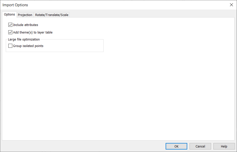
The Import Options dialog will appear.

Figure 9: Import Options dialog.
If the file already has Projection set, it will appear greyed out in Projection tab. Press OK to finish the import.
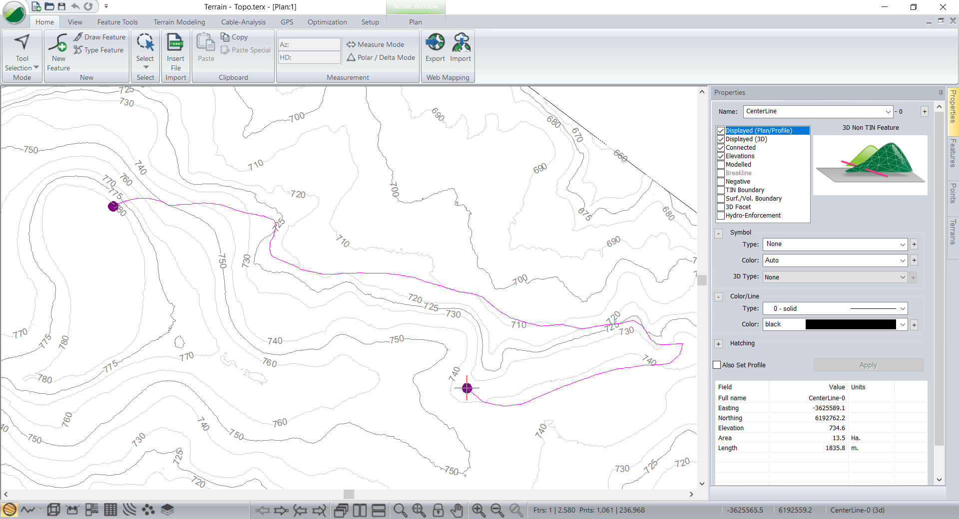
Your screen should look similar to image below.

Figure 10: Preliminary Road feature Imported.
STEP 3 - Path Exploration
- Select Optimization tab I Path Explorer AI:
You'll be prompted with a dialog similar to Figure below:
Figure 11: Path Explorer dialog.
The following parameters should be set.
- Target TIN Surface:
- Browsing to select a File.
- By selecting the Current TIN. (default)
- Resolution:
- Horizontal: Precision at which the search evaluates elements along the horizontal plane.
- Vertical: Level of precision used to evaluate elements along the vertical axis.
- Source / Destination: In this section, a feature can be selected whose endpoints will serve as source and destination coordinates of the path.
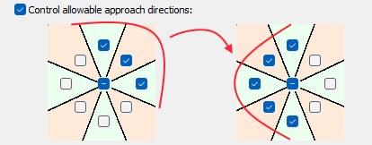
- Control allowable approach directions: This section allows the configuration of cardinal directions by which the path explorer feature can approach the source and destination point. This feature is quite useful when user wants to connect different road sections mantaining the direction of the road.

Figure 12: Control allowable approach directions.
- General parameters:
- Number of paths
- road width
- minimum horizontal curve radius can be set.
- Construction parameters: Select the Max. Cut/Fill, Min. or Max. Grade, Cut/Fill Slopes and Cut,Fill and Surfacing costs.
- Construction zones: Parameters that can be used to determine costs and constrains spatially. The user will be able to set No-Go Polygons, No-Go Polylines, Polygons and Polylines.
With parameters set, press OK to run Path Explorer.
For further information, please refer to the Youtube video shown below: