Construction Zones
Updated May 03, 2024
This article applies to:
- Softree Optimal
Construction Zone parameters can be used to determine costs and constraints spatially. If multiple zones are overlapping, only the parameters from the first one will be used.
Zone types:
There are 4 different types of construction zones in the Terrain module:
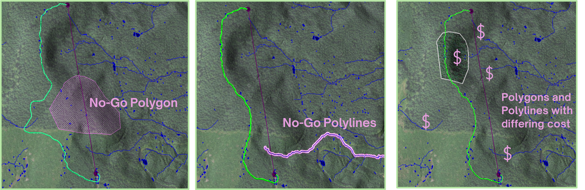
- No-Go Polygon: Polygons that must be excluded from all the construction.
- No-Go Polylines: Polylines that shouldn't be crossed during construction.
- Polygon Zones: Zones that share a common set of costs or constraints.
- Polyline Zones: Polylines that share a common set of constraints or crossing, embankment/excavation costs.
In this example, we will first run Path Explorer without adding any Construction Zones. Then, we will include construction zones in our optimization to better understand their role and importance.
Part 1: Path Explorer without Construction Zones

Figure 1: A - B feature.
In order to run Path Explorer, we require a Terrain Feature with a start and end point. Even if the feature is a multipoint detailed feature, all that matters is the start and end points of our feature (A and B), as shown in the image above.
- Create, then select a terrain feature (draped feature recommended)
- From the Optimization tab | Path Explorer AI to open the Path Explorer dialog box.
- Inside the Path Explorer dialog we set our variables and inputs, including initial parameters:
General Parameters
-
Number of paths | Desired number of paths. The search will attempt to generate a diverse set of potential paths, given the constraints.
-
Road width | The desired road width.
-
Minimum Hz Curvature | Minimum horizontal curvature radius allowed.
Construction Parameters
-
Min. vertical offset | Minimum allowed vertical offset measured from ground (0 is ground; negative is below ground).
-
Max. vertical offset | Maximum allowed vertical offset measured from ground (0 is ground; positive is above ground).
-
Max. grade (%) | Maximum allowed grade (%), considering direction Source → Destination.
-
Min. grade (%) | Minimum allowed grade (%), considering direction Source → Destination.
-
Cut cost |Cost per cubic unit of cut material.
-
Fill cost | Cost per cubic unit of fill material used.
-
Surfacing cost | Cost per square unit of surfacing material.
-
- Then, press OK to run Path Explorer.
Path Explorer will return solutions based on your topography, general parameters & constraints:

Figure 2: Path Explorer features.
Part 2: Including Construction Zones
Construction parameters can be used to determine spatial costs and constraints in Path Explorer. The following example will demonstrate the different types of construction zones that may be included.
Now, we will include new features to our model to set them as construction zones.
Set features as construction zones:
To set features as construction zones, these features should be included or created in the Terrain file.
You can insert these features by using the Insert File button located at the Home ribbon. Common files to include may include KML/KMZ and Arcview Shapefiles.
- Press the Insert File button and browse to find and select the file that contains the area to include as the construction zone. In this example, we will insert a Shapefile (.shp). Then hit OK.

Figure 3: Inserting a Shapefile.
The result of importing a shapefile:

Figure 4: Polygon inserted as a Shapefile into Terrain.
Although the polygon appears in Terrain, it is not included yet as a construction zone.
- Select the Optimization ribbon and press the Construction Zones button.
The dialog below will be prompted:

Figure 5: Construction Zone Parameters dialog.
- Press New... and use the drop-down list to select No-Go Polygons.

Figure 6: New Construction Zone Set dialog.
- Press OK button.

Figure 7: No-Go Polygon feature selected.
- Scroll to find and Select the feature that will be included as a No-Go Zone and Press OK twice to apply changes.
Running Path Explorer AI again with the same parameters we set before, we will get the following result.

Figure 8: Path Explorer features avoiding a No-Go Polygon.
Setting a block boundary
In some cases, projects may require setting a boundary where to search the paths. In that order of ideas, it may save a few clicks. Rather than creating a donut or a polygon that almost encloses the block, you could use the block boundary as a no-go polyline. Despite it being a polygonal feature, you can still use its boundary as a polyline.
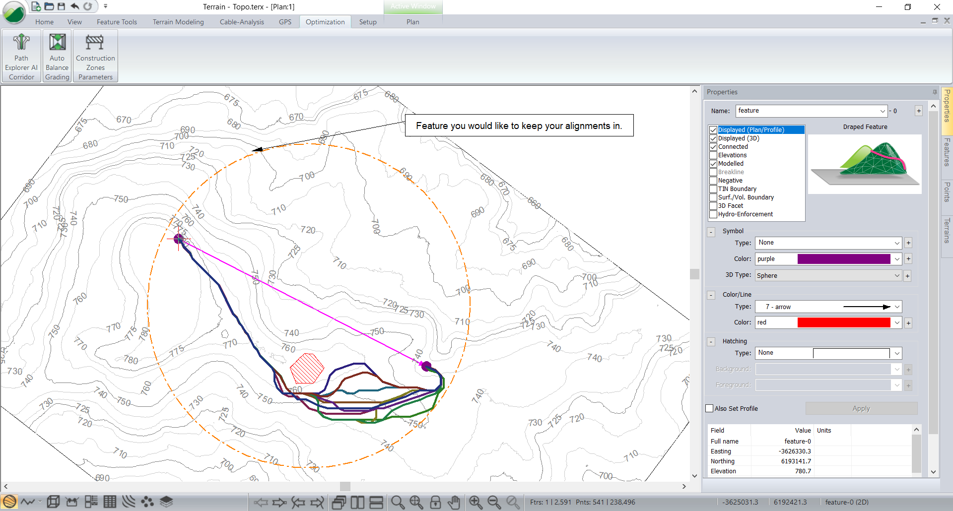
Figure 9: Boundary feature for Path Explorer.
Construction Zones close to Start/End points.
It’s worth noting that there is a zone around feature extents that interact with the resolution used in the algorithm. If your Start/End point is on or within the resolution of your no-go feature, it may see that as being in a no-go zone. The trick here is to adjust the boundary a bit so it has room to start.