Optimizing Long Corridor Projects
Updated May 27, 2024
This article applies to:
- Softree Optimal
Download the example files used in this tutorial: Long Road 1. zip
Extract / unzip prior to beginning the tutorial.
Defining a Large Problem
Large optimization problems can take a very long time to solve. One measure of problem size for Softree Optimal is the number of sampled stations; this is proportional to the length of the alignment. Another important factor is the Alignment Specification curve type in the Options, Standards Tab. Station sample spacing can vary (see Section Sampling and Accurate Costing), but if we assume 10 meters, the table below provides a rough guideline for maximum problem size.

Table 1: Recommended maximum problem size for vertical alignment optimization.
Note: There will be many exceptions to the guidelines above. Optimization solution times are very hard to predict.
Long Road Example
If you wish to optimize a long alignment (see table above) it is probably worth trying to solve to in one piece. If, however, the solver finds no solution in a reasonable amount of time, you will need to break the problem into segments. You are the one to define reasonable amount of time; optimizations can sometimes take hours or days.
In the example below, we will divide the alignment into three pieces, optimize each piece and merge the resulting alignments into a final single alignment.
Is this a Long Road?
1. Open the Location module application.
2. File | Open. Select LongRoad.dsnx. Press Open.
This design has one vertical alignment named Initial; you can see this in the Project Explorer panel on the right hand side of the screen.
3. Press the ![]() button next to H-align, then right-click on the Initial:entire alignment in Project Explorer and Press Vertical Options... in the Alignment Properties panel.
button next to H-align, then right-click on the Initial:entire alignment in Project Explorer and Press Vertical Options... in the Alignment Properties panel.

Figure 1: Vertical Optimization Options, General tab, showing number of Sections sampled
In the General tab, note that the number of Sections sampled is 1391. In the Standards tab, note the alignment specification Curves and tangents [Slow] has been selected. This is a large problem according to Table 1 above.
4. Press Cancel to exit the options dialogue.
5. Right - click on Initial V - alignment and select Vertical Optimization... Press Process button.
A Warning dialogue box will appear; this allows you to know the size of the problem of your optimization setup before you run the optimizer. Note the different options that RoadEng is suggesting to go through this issue.
6. Press Cancel button in the dialog.

Figure 2: Location dialogue box showing the large problem warning
Define Segment 1
Now we will define a station range to represent our first segment.
9. Create a new alignment with limited station range:
- Right-click I Add Vertical... I to open the Vertical Optimization Options dialogue box.
- Change the Name to “Segment 1”
- Change the Description to “0 to 11700”.
- Under Station Range, uncheck All. Set the Station Range from .. to 11700.
- Set the Sections sampled with a Spacing of 24.
- Press the Tab key or click in any white space to update number of Selected points
The General tab of the options dialogue box should look like the figure below.

Figure 3: Restricting the Optimization Range
Note that the number of selected points has been reduced to 490, slightly below our threshold.
Note: The “long road” threshold used by Softree Optimal is somewhat arbitrary; different computers will solve the same problem in different times. In addition, different problems with the same number of points and the same curve settings will often take significantly different times to solve.
The other settings have been prepared for you; take a look at the other tabs if you’re curious.
- Press OK to close the options dialogue box. Press OK when the Recalculate Range dialog appears.
- Ensure Segment 1 alignment is selected.
- Go to Corridor I Delete Range I Turn off All Points checkbox and set the Range from 11700 to .. as shown below.

Figure 4: Delete Range for Segment 1.- Press OK.
Note: With the last step above, you have deleted the vertical from Stn. 11700.
10. Create a vertical alignment:
- Right-click on Segment 1 I Vertical Optimization...I Press the Process button to run the Optimization.
Note: There is no Warning this time.
- Press the Proceed button in the Optimization Control dialogue box.
On our test computer, the Pre-Process took about one minute. Then it took another minute to find a solution with Optimality Gap of about 10%.
- Finally press OK to close the Log report.
The costs shown are for the range [0, 11700]; in the profile window, observe that the new optimal alignment (magenta) stops at station 11700.
Define Segment 1 Optional
11. Merge Segment 1 into the current alignment:
- Make sure Initial alignment is selected.
- Right-click on Initial alignment.
- Select Merge... button.
- Use the drop-down list to choose the Segment 1 vertical alignment.
- Press OK.
- Wait for the recalculation.
This operation merges the optimized alignment First section with the current alignment. There is a discontinuity at station 11700 but, as we will see below, this is not a problem. Note that if you decide to re-cost the current alignment, it will only calculate over the interval [0, 11700].
Define Segment 2
To prevent the need for material movement between optimized segments, we want to start the next segment at a zero crossing in the Mass Haul diagram.

Figure 5: Hover tip in Mass Haul diagram shows zero crossing near station 10880
Note: It is not always possible to end your first segment with zero accumulated volume. In this event, create a fixed (not variable) pit in your second optimization to account for the surplus or deficit (Pits tab in the options dialogue box).
12. Create another segment:
- With Segment 1 alignment selected in the Alignments list, press the Add Vertical...button.
- The name is now “Segment 2” (automatic).
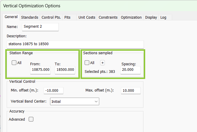
- Change the description to “stations 10875 to 18500”.
- Under Station Range, set the Station Range from 10875 to 18500.
- Leave Sections and Vertical Control set to 20.

Figure 6: Selection of Second Alignment Range
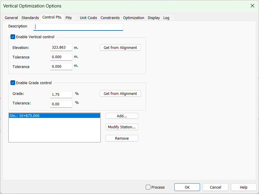
In order for the start of the second segment alignment to match the end of the first segment, a control point must be created.
13. Create a control point to ensure continuity:
- Click on the Control Pts. tab.
- Select and Remove the control point at station 0.0 (outside our station range).
- Press the Add button and enter 10875 (or select Start of alignment). Press OK.
Note that the Elevation value is already set correctly (click to the Get from Alignment button if you are not sure).
- Set the Enable Grade Control check box.
- And press the associated Get from Alignment button to set the Grade value as shown below.
- The Description is optional.
- Press OK to close options.

Figure 7: Control point to ensure continuity of second optimized range
Now we’ll optimize the second segment.
14. Right-click on Segment 2, Vertical Optimization... and Process. Again, waint until a solution is found and select OK when the Log appears.
15. Corridor I Delete Range I Turn off All Points checkbox and set the range From ".." to 10875.
16. Again, select Initial alignment, right click and Merge. Notice that the alignment is smooth and continuous at station 10875.
Define the 3rd and Final Segment
16. Repeat the above process for the last section in the road (specify the station to value with “..” as shown in the figure below).
- Set Initial Alignment 2 to Current, Merge Segment 2.
- Find a Mass haul zero before the end of the last segment (station 18500).
- Create a New V-alignment: Add Vertical ...:“Segment 3”.
- Add Control point to ensure continuity.
- Optimize.

Figure 8: Final segment, set end stations to “..”.
Create Complete Alignment
When you have completed the final segment. Delete the V-range from ".." to 17960. Then, Set the Initial alignment to Current, Merge operation. Probably, you would like to look at the cost and haul information for the entire 27 km. We do this by creating one more vertical alignment.
17. Create the final combined alignment:
- With the Initial alignment (the current alignment) selected, press the Add Vertical...button.
- Change the name to “final”.
- Change the description to “entire road optimal”.
- Under Station Range, set the All check box.
- Leave Sections and Vertical Control areas as is; we will not optimize this alignment.
- Press OK to close options.
This alignment contains all the merged alignments.
18. Press the Set Current button.19.When the volumes calculation is finished, Re-Cost the selected alignment:
- Press the Re-Cost button to open the Re-Cost dialogue box.
- Keep the existing options and press the Re-Cost button.
The costs and Haul Graph now show the complete design. You also have all the component segment alignments if you want to review the process or repeat any portion.

Figure 9: Combined alignment.
20. File | Exit.Do not save the design.