Defining Sub-Surface Layers
Updated August 22, 2024
This article applies to:
- RoadEng Civil
- RoadEng Forestry
This Knowledge Base article is an excerpt from one of our tutorial files. The files referenced in the article, as well as the full tutorial document, are available in our Tutorial Installer.
Note: Refer to Getting Started section for file install folders (<RoadEngCivil> and <Defaults and Layouts>).
 File | Open <RoadEngCivil>\Location\Align stage 4.dsnx.
Select Home | Ground Types Editor button.

Figure 1: The Available Ground and Subgrade Fill
Materials in the Ground Types Editor.
Create a new ground type for use in subgrade fill:
-
Select the FR Fractured Rock item.
-
Press the New… button to open the New Ground Type dialogue box (figure above right). Note that we start with a copy of the selected item.
-
Note: The Composite Material option can be used for uncertain or mixed materials found in the original ground – F1 for help.
-
Fill in the ID RR and Description Rip Rap.
Note that the RR fill angle is set to 100% (1:1); this is suitable for our purposes, so there is no need to change it. The cut angle is not important as we will not assign this material as native ground.
Also create a material called CS-Clay Silt with cut angle 1:1 and fill angle 3:1.
Note: The default ground table is called NORMAL.GDX.
Press OK to accept changes and close the Ground Types Editor. Respond Cancel to the recalculate prompt (we didn’t change anything that is in use).
Assign original ground materials to a station range:
-
Group Home | Assign by Range
-
Select the Sub Horizons tab (Figure 17‑2 below left).
-

Figure 2: Defining Materials in The Original Ground.
-
Press the
button beside the Ground Layers field to open the Ground Layers dialogue box (Figure 17‑2 above right).
Note: If you define reference surfaces (Terrain files with a DTM) you can use them to define the C/L depth values. This would require bore hole data or like create enough subsurface points to make surface models.
-
Select the three subsurface layers shown above (OB, CS, FR) and then set the layer depths (1, 5).
-
Press OK to close the dialogue box and fill the Ground Layers field in the Sub-Horizons dialogue box.

Figure 3: Sub-Horizons Have Been Applied to The Entire Alignment
-
Leave the From/To Stn. values as “..” and press the Add/Edit button. This will apply the new layer arrangement to the entire alignment.
Note: The most common mistake made in the assignments dialogue box is to skip the Add/Edit step. If you Press OK before the ranges are updated, nothing happens.
Press OK to accept changes and close the dialogue box.
Respond OK to the Re-calculate Range prompt.
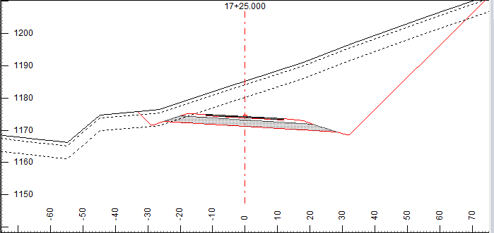
Select a cross section that has some cut in it. Notice that the new ground layers are displayed.

Figure 4: Ground Layers Depicted in The Section Window.
The design total volumes haven’t changed because of the new ground layers. However, the program is now keeping track of three categories of cut volume which can be reported separately.