Class Label Formatting
Updated August 22, 2024
This article applies to:
- RoadEng Civil
- RoadEng Forestry
This Knowledge Base article is an excerpt from one of our tutorial files. The files referenced in the article, as well as the full tutorial document, are available in our Tutorial Installer.
The Plan Window is used in the following example but the same principles apply to the Profile and Section windows.
 File | Open <RoadEngCivil>\Location\Align stage 8.dsnx.

Figure 1: Align Stage 8.dsnx
This example demonstrates how to display:
Station labels at reporting points (set at 200ft intervals)
Horizontal curve labels at the IPs
Culvert description labels.
These label types are representative; other labels behave in a similar way.
To create labels at equal intervals, you need to set up Report Points to generate cross sections where you want your labels. Most labels can only be displayed at existing cross sections.
In the plan view window, right click | Plan Options… | click on the
button next to Report Points. This will open the Report Point Properties dialogue box. Select Auto Interval Points 2 to create points on 200 ft intervals (figure below). Press OK twice to return to the main screen.

Figure 2: Report Point Properties Dialogue
Set up station label options:
Right click, select Plan Options…
Click on the
button beside Labels to open the Label Selection and Formatting dialogue box.
Turn on LStn Report Points (Intervals) by double clicking (or select, then set the Display check box).
Note: LStn stands for Location Station
Set the Interval spacing to 200 (Figure 22‑4).
Press OK twice to return to the main screen.

Figure 3: Plan Window Label Selection and Formatting
After the Plan window refreshes the screen should appear with stationing every 200 feet.
The format of the stationing (xx+yy in this case) is controlled in Setup | Location Setup | Units tab | Stationing: Traditional S+dd e.g. 12+01 from dropdown.

Figure 4: Stationing at Fixed Intervals
Next, horizontal curve information is added. Another option is to use the Curve Tables in the Multi-Plot window (see Multi-Plot Report Builder ).
Set up curve labels for display:
Again, open the Plan Label Selection and Formatting dialogue box. Right Click | Plan Option… | plus sign next to labels.
Turn on display of Horizontal IP's at Curves.
Press OK, OK to return to the main screen. Notice the curve radius labels.
Some labels have configurable content. In the next section, we will add to the contents of this label.
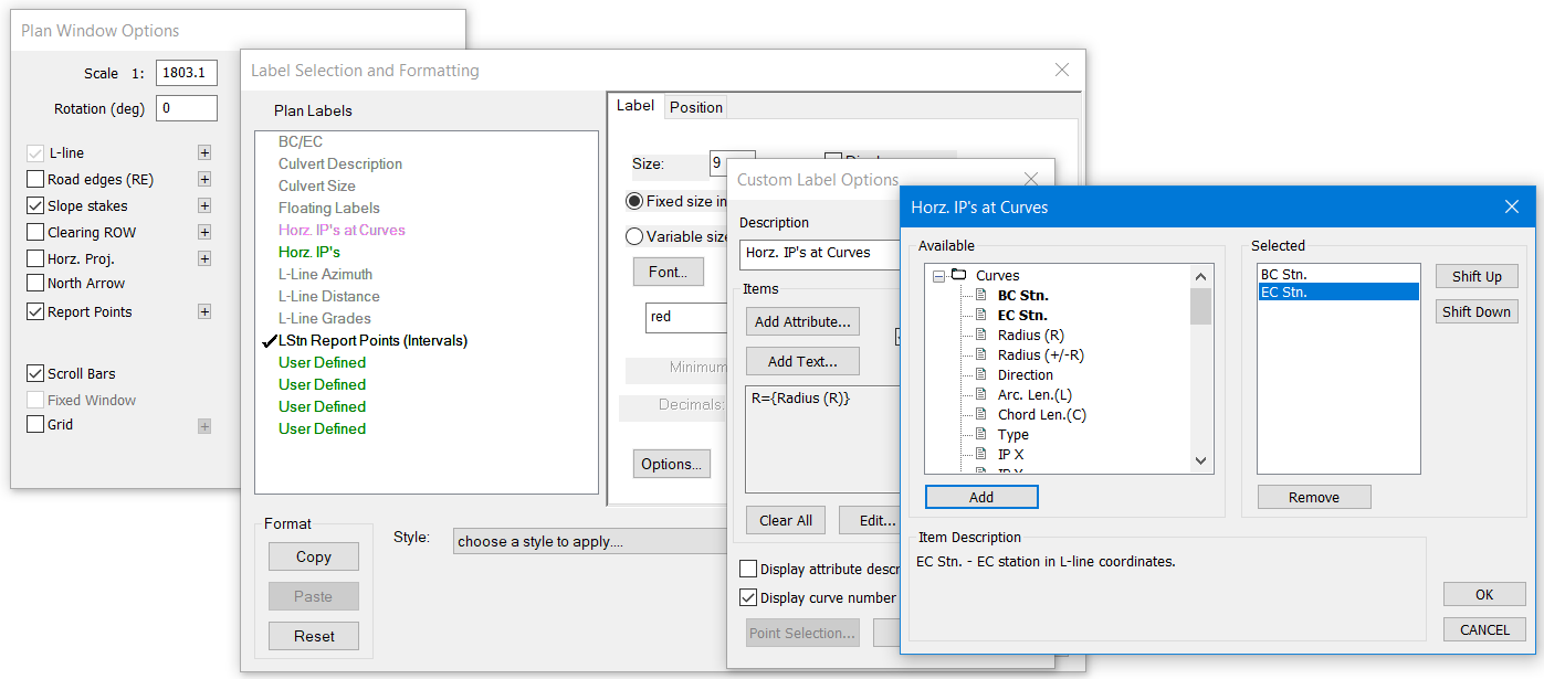
Add Begin Curve (BC) and End Curve (EC) stations to the Horizontal IP's at Curves label:
Open the Plan Label Selection and Formatting dialogue box.
Select Horizontal IP's at Curves and click on Options… button.
Note: Label classes shaded green will have Options available. Refer to the
section below.
Click on the Add Attribute… button and then add BC Station and EC Station (Figure 22‑6).

Figure 5: Displaying Horizontal IP’s Labels at Curves
.
Press OK to update the Items list.
Press OK three more times to return to the main screen.
Notice that the additional BC/EC information is now displayed (Figure 22‑7).

Figure 6: Curve Information Labels
There is a pre-configured label called BC/EC; you might want to use this as an alternative to displaying station values at the curve IP.
To turn on labels for the attributes that were just added: Plan Options… |
sign next to labels | Select Hoz. IP’s at Curves |Options… | check Display attribute descriptions.
Now we will display a label at the culvert just before station 14+00. We will also look briefly at the Position formatting.
Add a culvert information label:
Open the Plan Label Selection and Formatting dialogue box.
Select Culvert Description class.
Select the Position tab (Figure 22‑8).

Figure 7: Culvert Information Labels
Change the Connector combo box to Circle.
Press OK twice to return to the main screen.

Figure 8: Culvert Pipe Display
At this point you may want to experiment with some of the Position options to see how they modify the label formatting; see also <F1> help..
Note: It is possible to use Point Label Formatting (see section below) to modify the Position settings for the class.
 File | Close. Do not save changes.