Assigning a Culvert
Updated August 22, 2024
This article applies to:
- RoadEng Civil
- RoadEng Forestry
This Knowledge Base article is an excerpt from one of our tutorial files. The files referenced in the article, as well as the full tutorial document, are available in our Tutorial Installer.
In this exercise, you will assign a culvert to the road realignment design.
Note: Refer to Getting Started section for file install folders (<RoadEngCivil> and <Defaults and Layouts>).
 File | Open <RoadEngCivil>\Location\Align stage 7.dsnx.
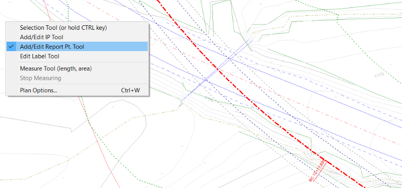
In the plan window, zoom in to the creek crossing (figure below).

Figure 1: Creek Crossing Location; You Can See the Old Culvert in the Background
Right click in the plan window and choose Add/Edit Report Pt. Tool (
Figure 2: Report points can only follow the existing alignment.

Figure 3: Desired Culvert Location
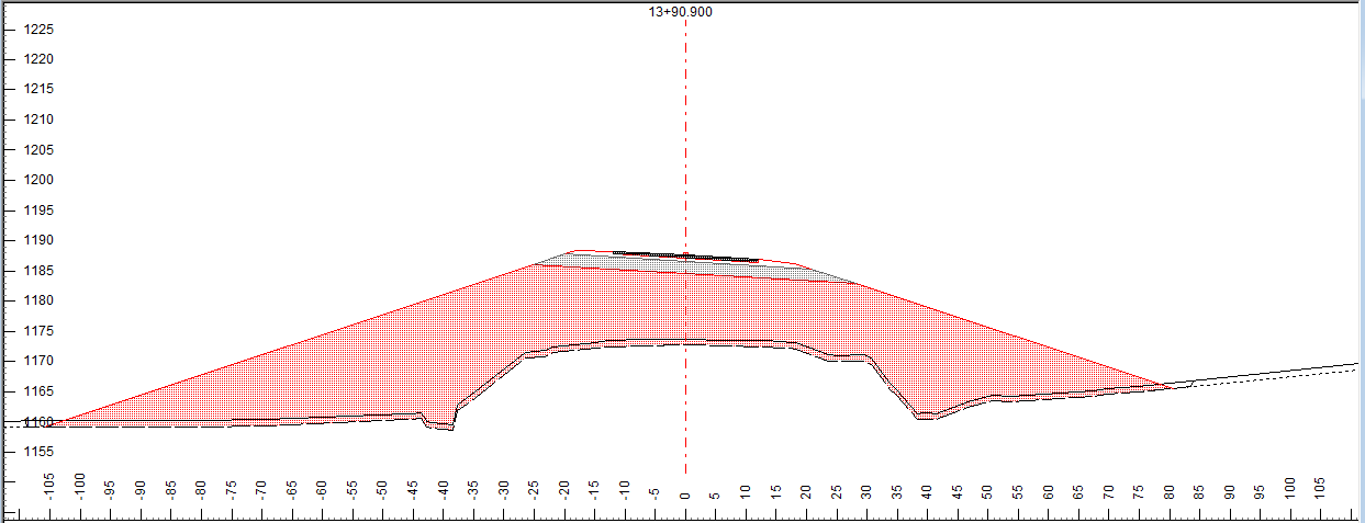
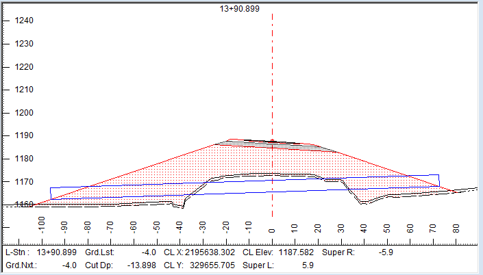
Select screen layout <Defaults and Layouts>\training\training Culvert.dlt. Your screen should look similar to the figure below.

Figure 4: Screen Layout Training Culvert.dlt
Press Add… in the Culverts Panel (right side of screen) to open the dialogue box shown below. Note that the Station defaults to the current cross section.

Figure 5: Add Culvert Dialogue Box
Set the Natural channel (stream) check box (the alternative is a cross drain). Press OK to create the culvert.
If the profile window is not showing the correct station, press the next
and then back
buttons in the tool bar. Whenever you change the current section this way all windows scroll depicting the new current points. Your culvert should be visible in all three windows.
Press Properties… (top left of Culverts panel) to open the dialogue box shown in Figure 21‑5.

Figure 6: The Culvert Properties Dialogue Box allows the user to change
the Location, Size and Shape of a Culvert.
Change the Diameter to 60 inches and press OK to close the Culvert Properties dialogue box.
Change dropdown menu to “Cut depth to C/L to structure bottom” the Depth to 8 feet, figure below left and Press Apply button to see the changes.


Figure 7: Culvert Elevation Controlled by Cut Depth
at Center Line (Left) and by Catch Points (right)
Change the Vertical Position type to Attach to upper ditch/catch point, figure above right. Press Apply to see the changes.
The latter method (Attach to upper ditch/catch point) is more reliable for creating a stream culvert that sits on the bottom of a stream bed.
Press the Save… button in the culverts panel. Check off the Save to disk for future designs box and respond OK to the save stream default prompt. The next time you create a Natural Channel culvert this will be the initial configuration.