Setup of Alignments and Surfaces
Updated November 30, 2017
This article applies to:
- RoadEng Civil
This example will demonstrate how to calculate the volume between an original ground surface and final grade surface.
Prior to starting this example, the following TIN surfaces were created from re-measure survey data:
| OG.terx | original ground |
|---|---|
| FG.terx | final grade |
We have also placed the centerline alignment in OG.terx as a ‘draped feature’ (Properties set to Modeled but no Elevations).
First step is to create a new Location design.
Note: Refer to Getting Started section for file install folders (<RoadEngCivil> and <Defaults and Layouts>).
Open the Location module.
 File | New File. Press the Browse… button and open the original ground terrain. <RoadEngCivil>\As-Built\OG.terx.

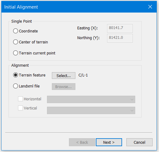
Figure 1: Initial Location Dialogue
Note: This example is in Metric Units. If you get the following warning, it indicates that your project units will be changed to metric for this example. Press Continue.
In the Initial Alignment Dialogue Box under Alignment select Terrain feature C/L-1|press Next> button.
-
Check Fix Sections box;
-
Click on Browse… find the file.
Load file: <RoadEngCivil>\As-Builts\FG.terx
-
Section spacing: 25.0
-
Finish button
View | Retrieve button, select file: <Defaults and Layouts>\Normal.dlt
Close the horizontal and vertical curve panels and open the Section Editor by press the button
 .
.In the Cross Section panel, you can see the section are spaced at 25.0 m. The red line represents final grade and the black line represents original ground.
To display cut and fill volumes: Right click in data window | Data Options… | Columns… button | Remove all attributes except L-Stn| expand
 Volumes General | Add Cut V. & Fill V.
 Data in the data window will be displayed at stations the same as the fixed cross sections. To change stations displayed one must first delete the fixed sections: Left click on
 Fixed Sections | right click | Remove… | OK
In the Cross Section panel, Add Section… button | Select Station Range button |
below Point Types | Select All button, uncheck Include | Select Auto interval points (20.0m) | Properties... button | Check Automatic and set Interval to 10 m (or whatever is required.) | OK | OK | OK. You can view the cross sections by clicking on the stations in the Cross Section panel.
 File | Close.