Multiple Surfaces
Updated November 30, 2017
This article applies to:
- RoadEng Civil
- RoadEng Forestry
This exercise will use the same surfaces as the previous exercise OG.terx (original ground) and FG.terx (final grade) plus two additional surfaces:
| WG.terx | Waste surface after stripping of topsoil |
|---|---|
| UC.terx | Undercut (or sub-cut) surface |
In Location,
 File | New choose Terrain Surface | Browse.. button <RoadEngCivil>\As-Builts\OG.terx
Select Alignment: Terrain feature, C/L-1 | Next> button | check Standard Template |Finish button.
View | Retrieve button, select file path <Defaults and Layouts>\training\training as-built.dlt.
Setup | Location Setup | Alignment tab | Set L-line Start Station 0.0.
-
Define the reference surfaces. These surfaces are used for display and control of templates and volumes. These surfaces will be stripped, undercut, and final surfaces. Still within in the Alignment tab of Location Setup dialogue press Terrains… button.
-
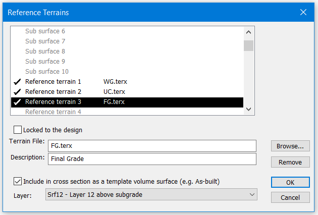
Scroll down in the surface list and select Reference terrain 1.
Click the Browse… button select file: <RoadEngCivil>\As-Built\WG.terx | Open
Type in Description: Stripped Surface
Check Include in cross section as a template volume surface (e.g. As-built)
In Layer dropdown set the layer to: Srf10 – Layer 10 above subgrade
OK button
Similarly, set Reference terrain 2: UC.terx, Description: “Under-Cut” and Layer: Srf 11 - Layer 11 above subgrade
Similarly, set Reference terrain 3: FG.terx, Description: “Final-Grade” and Layer: Srf 12 – Layer 12 above subgrade
Press OK twice to return to the main screen.

Figure 1: New Location Start Coordinates Dialogue
Note: The order of reference terrain layers is important if we are to get realistic volume calculations later. They should be in chronological order: stripping before under-cut before final grade.
Home | Templates button to open the Template Editor. Click on the Open Table… button (upper left), <Defaults and Layouts>\training\Training AsbuiltSurfaces.tpl
Click on the Materials… button (upper window) to open the dialogue box shown below.
Scroll down and you will notice that material descriptions have been set for Srf10, Srf11 and Srf12.

Figure 2: As-Built Surface Descriptions
Note: Material names are stored in template tables (and the template table is stored with the design document).
Material line type, color and hatch information is stored with screen layout files. The one you see now came from settings stored in Training As-Built.dlt
Press Cancel button to return to the template editor and OK to return main screen.
Press Cancel button to the Recalculate Range dialogue box. For only the as-built surfaces to be included the calculations, the design template needs to be disabled.
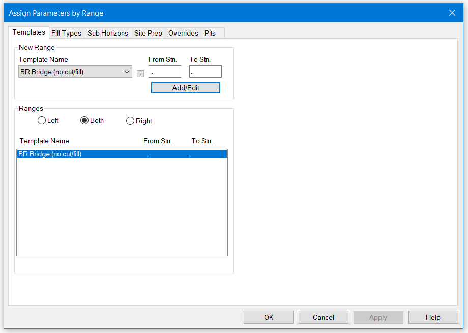
Home| Assign by Range button
Select the Templates tab (if it is not already selected).

Figure 3: Template Assignments
In the Template Name: select BR- Bridge (no cut/fill) from dropdown menu. Ensure that the From Stn. and To Stn. are set to “..”.
**Press the Add/Edit button** Press OK button to return to the main screen and OK button to Recalculate range.
Jump to Station: Section | Jump to Station button or <ctrl-J>; type 85 in the station field and Press OK to set the current station and update the cross section. Your screen should now look like the figure below.

Figure 4: As-Built Surfaces
The Data Window displays a volume report and cross section graphics based on our re-measure surveys. In many cases we could stop here, however, in this case there is one obvious problem with the volume calculations. WG (stripping) should never fill.

Figure 5: Section With Stripping Fill Area Shaded
The figure above shows how the stripped surface extends outside the original ground surface on the left (station 85); this generates the large fill shown in the volumes display. The WG surface needs to be tied off so it does not extend outside OG.