Calculating a Stockpile's Volume with a Laser Rangefinder
Updated September 23, 2019
This article applies to:
- Terrain 3D
- Terrain Forestry
- RoadEng Civil
- RoadEng Forestry
- Softree Optimal
This article explains how to calculate a stockpile's volume with a laser rangefinder (TruPulse-360R model). To download the survey file (pile1.tr1) please Click here.
Laser rangefinders are used in the field to determine distances of objects and take survey notes. RoadEng 8 allows you to do this seamlessly by connecting to your rangefinder via Bluetooth and importing data instantly to the Survey/Map module. Just pair the device with your computer (or Window's 10 tablet) and you’ll be able to enter your survey notes using the laser rangefinder. Click here for step-by-step instructions on how to pair and set up your device.
Using Rangefinder for Surveying a Stockpile's Volume.
Follow the below steps in the field to import data and calculate the stockpile's volume.
- Open the Survey/Map Module.
- Open a new traverse: Home | New Traverse | Select Traverse Document | OK.
- Accept the defaults Starting Coordinate position and set the screen layout to laser.slt.
- Change the Shot Type to Radial Shot in the active row and put the target instrument hight in the related cell.
- Make sure the instrument is connected to the computer and start taking a shot by zooming to the first point and press the FIRE button.
- A window appears on the screen that shows Shot Type, Horizontal Angle, Vertical Angle and Slope Distance. Click on the Enter Shot button and automatically data will be brought into the table.
- Add toe/top as a label(comment) in the last column for each shot.
- Continue to survey the pile by repeating steps 5 to 7 for other points.
- If you have changed your location during the survey, change the Shot Type to Fore Shot for those locations.
- Save your data table as a TR1 file.
- Open the Terrain Module. File button| Open. Navigate to find the TR1 file of the survey (make sure to change the file type to *.tr1). Select the file and press OK.
- Right-click on the screen, select Activate Window (Plan) Options. In the Labels tab select the Comments (Survey) and press OK.
- Select all items on the screen and in the Feature Properties box, un-tag the Connected option and hit the Apply button.
- Click on the New Feature icon, in the Feature Properties box tag the connected option and type toe as a name for the feature. Click on the Mouse button and connect all toe points by creating a polyline.
- In the Terrain Modeling tab, hit the Generate TIN button and set the Terrain Calculation window according to the below figure and Press OK.
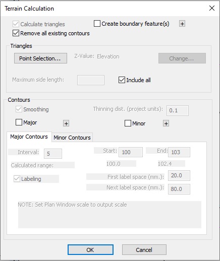
Figure 1: Terrain Calculation dialog box
16 - In the Terrain Modeling tab, Click on Calculate Volumes icon and press OK to see the total cut/fill volume.
The below figure shows the 3D view and plan of the pile.
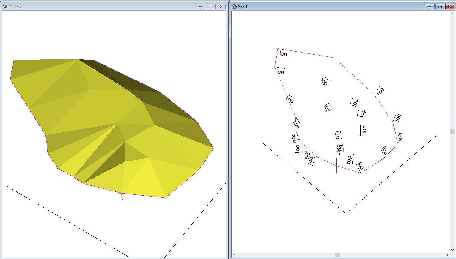
Figure 2: 3D view and plan of the pile
To watch the video contains all of the above steps please click here.