Alignment Design & Balancing Example
Updated May 08, 2025
This article applies to:
- RoadEng Civil
- RoadEng Forestry
This Knowledge Base article is an excerpt from one of our tutorial files. The files referenced in the article, as well as the full tutorial document, are available in our Tutorial Installer.
This project has the following goals and constraints:
- Realign less than 2500 feet of road.
- Increase design speed to 40 mph.
- Grades less than 8%.
- Tangent to existing road (vertical and horizontal).
- Balance sub-grade volumes.
- Minimize cut and fill volumes.
- Minimize right of way (road foot print).
- Template constraints:
- Lane width.
- Shoulder width.
- Material types.
- Material thicknesses.
- Cut and fill slopes.
- Vertical Curve constraints:
- Design speed.
- Sight stopping distance.
- Horizontal Curve constraints:
- Design speed.
- Super-elevation.
Our goal here is to adjust both vertical and horizontal alignment within the constraints given so that we minimize and balance volumes. We start by assuming that the template given is correct.
Note: Refer to Getting Started section for file install folders (<RoadEngCivil> and <Defaults and Layouts>).
 File | Open <RoadEngCivil>\Location\Align stage 3.dsnx in Location Module.
The outermost lines on either side of the alignment are the slope stakes or catch points (configurable in the Plan Options dialogue box). The area inside the slope stakes is the footprint of the road that must lie within the right of way.

Figure 1: Green Dot Slope Stakes (catch point) Lines in
the Plan Indicates the Footprint of the Design
- Press the Activate Profile Window button
 , in windows toolbar, to open the Profile window using the in the windows toolbar and notice shape of the ground and the quantities indicated by the mass haul diagram (figure below).
- Enter selection mode (right click | choose Selection Tool) then click on the alignment
 to view a cross section in the middle of the through cut (red cross in the profile shown below).

Figure 2: The Road Passes Through a Hill and Therefore has Large Cut Volume.
- Press Activate Plan Window button
 , in windows toolbar. You can see the contours representing the hill under the current point.
 - Press Activate Horizontal Curve Panel button
 , in windows toolbar. To navigate Previous IP
  or Next IP
  buttons to the first curve.
 - Check the Use Minimum Radius box (figure below). Notice that the radius can be reduced to 600 ft without reducing the design speed.

Figure 3: Use Minimum Radius Checked Defines the Smallest Curve
Possible Given Design Speed, and The Super-Elevation Table
- Apply the smaller 600 ft radius to both curves. This will give you some room to move the horizontal alignment so it is not so far up the hill.
- Change to edit mode ; right click choose Add/Edit IP Tool.
- In the Plan window, move C1 (the IP for the South curve) North and move C2 (the IP for the North curve) South (both while maintaining tangency with the old road).
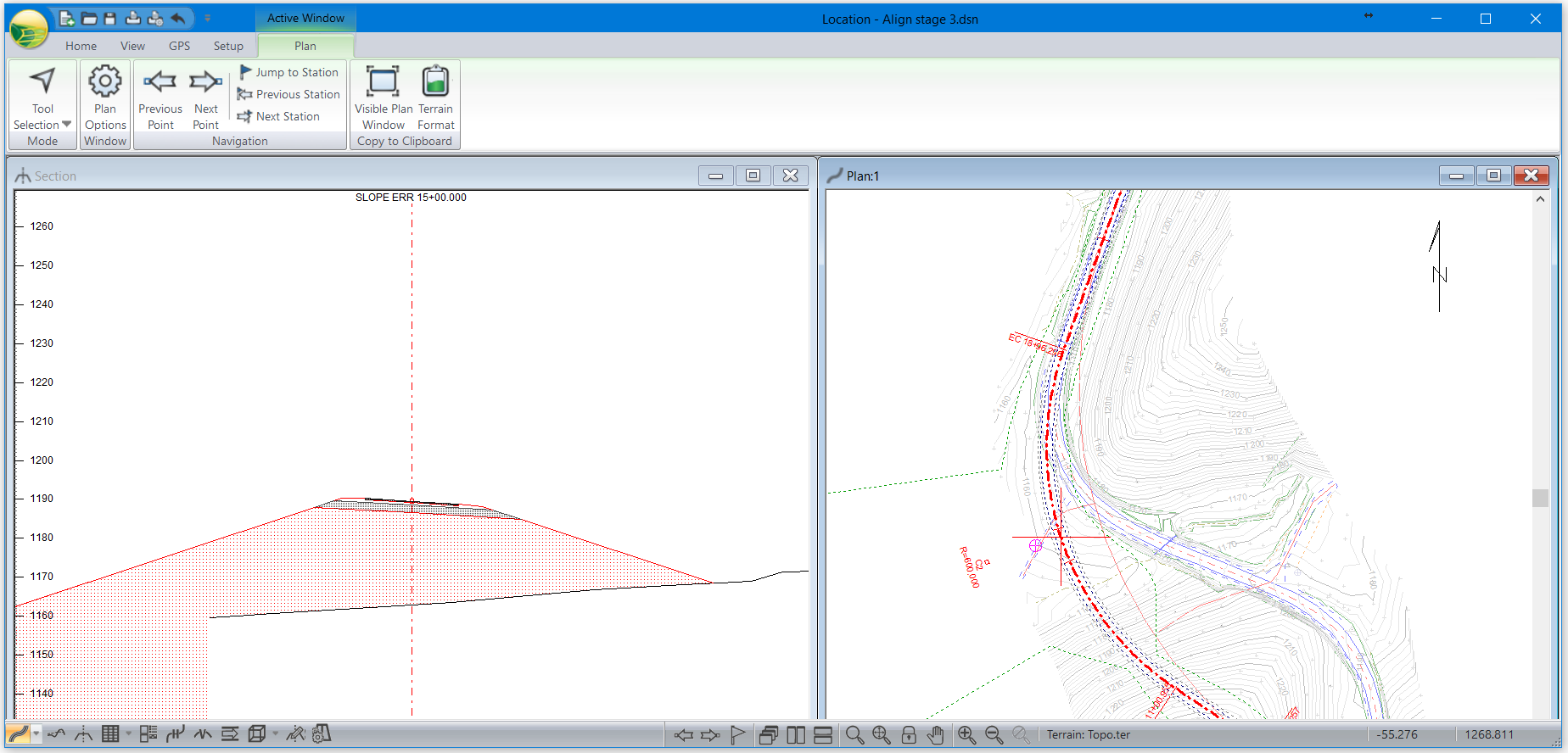
- If you move the C2 too far south, the cross section will extend beyond the edge of the surface model (figure below). Be sure that the fill areas of the road do not fall off the topographic surface. You will never be able to balance the mass haul diagram this way.

Figure 4: Plan and Section Windows Depicting what occurs When The Road Section Extends Beyond the Original Ground Surface Model
- Note that a captured curve IP will stop moving (and there will be an audible beep if you have sounds on) when the curves bump into each other and become an S curve.
- Open Activate Profile Window button
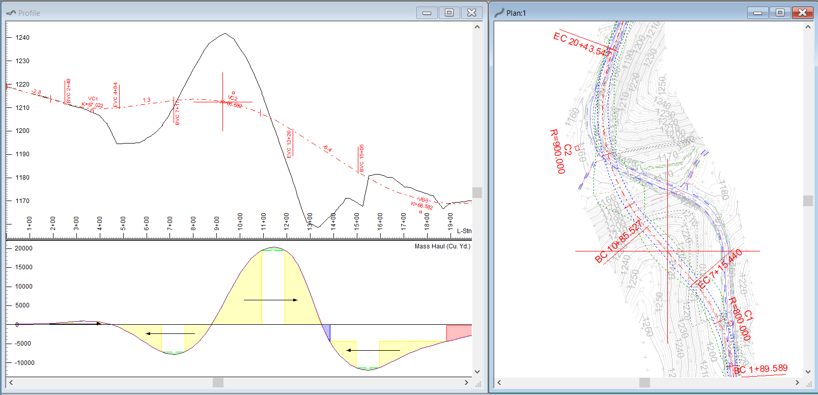
 and notice the new shape of the ground (figure below).

Figure 5: Alignment Closer to the Old Road
(but still 40mph) Significantly Reduces the Volumes
- Adjust the vertical alignment to balance the volumes; use the mass haul diagram (figure above shows an almost balanced Mass Haul).
In Figure 14‑5 above, the material cut to pass through the hill is about 28,000 cu. yds. (8000 + 20000). After the grades have been reduced alignment the footprint becomes smaller.
Your design will be different from the example in the figure, but you can use the same techniques to quickly evaluate its quality.
- Note that it may be considered unsafe to have an S curve. Continue modifying the design until you are comfortable with:
- Vertical and horizontal IP editing (including adding and removing IPs).
- Vertical and horizontal curve editing.
- Moving around the various Location windows.
 File | Close. Do not save changes.