Calculating Stockpile Volumes Using Average End Area Method
Updated January 09, 2017
This article applies to:
- Terrain 3D
- Terrain Forestry
- RoadEng Civil
- RoadEng Forestry
The data sets referred to in this example can be downloaded located in the Stock Pile Volumes folder available here.
Download the PDF version of this example.
This example will demonstrate how to calculate the volume between several as-built surfaces (original ground, stripping and final surface) using the Average End Area method.
Prior to starting this example the following TIN surfaces were created from re-measure survey data:
- OG.ter - Original Ground
- Strip.ter - waste surface after the stripping of topsoil
- Final.ter - undercut (or sub-cut) surface.
Creating a Baseline
In order to calculate Average End Area volumes it is necessary to create a baseline (centerline) alignment.
1. Open the Terrain module and choose menu File | Open, select OG.ter
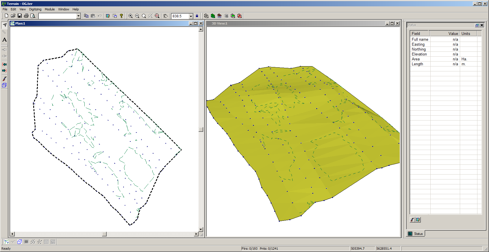 Figure 1: OG.ter
The next two steps will create a 'draped' centerline feature.
2. Choose menu Edit | New Feature. Set the feature properties as shown in Figure 2 below and click on Mouse.

Figure 2: OG.ter
3. In the Plan Window draw a
centerline feature as show in Figure 3.

Figure 3: Drawing the Centerline Feature
4. Save the Terrain file with the
centerline feature selected.
Creating a New Location Design
First step is to create a new Location design.
1. Open the Location module and choose menu File | New.
2. When prompted open the original ground terrain \StockPileVolumes\ OG.ter.When the New Location start coordinates dialog appears,
choose Terrain current feature, all points.

Figure 4: New location start
coordinates dialog.
The selected option will read the initial alignment from the original ground terrain. Next step is to retrieve a screen layout (StockPiles.dlt) to ensure your screen displays matches the screen displays in this example.
3. File | Retrieve Screen Layout and open StockPiles.dlt.+

Figure 5: New location design.
Note: Reference surfaces are used for display and control of sections and volumes. For this example they will be set to stripped, and final surfaces respectively.
4. Select Module | Setup to open the Location
Setup dialog box below. Select the Alignment tab click on the Terrains button to open the dialog box
below.

Figure 6: Setup Dialog
5. In the current dialog box (figure above), scroll down in the surface list and select Reference terrain 1. Click the Browse button and Open file Strip.ter.
6. Similarly, set Reference terrain 2 to Final.ter.
7. Press OK twice to return to the main screen.
Setting Up the Cross Sections
Now to setup the As-built surfaces descriptions.
8. Choose menu Edit | Edit Templates (or use Edit Templates toolbar button ) to open the template editor. Click on the Open Table button (lower left), browse to the folder containing this example and Open Stockpile\FollowSurfaces.tpl .
9. In the tree control select the first Follow Surf. II component (in the Follow Surface template). Click on Properties. Set the Horizontal Extent to 50 and the Surface to Reference terrain 1 (Strip surface) and press OK.

Figure 7: Component Properties
10. In the tree control, select the second Follow Surf. II component (in the Follow Surface template). Click on Properties. Set the Horizontal Extent to 50 and the Surface to Reference terrain 2 (Final surface). Press OK twice to return to the main screen.
11. Choose menu Edit | Assign Parameters by Range | Templates. Select the Follow Surface template, and press Add / Edit. Press OK to return to the main screen.
Setting Up Fixed Sections
Fixed sections allow you to easily display and edit cross sections.
12. In the Fixed Section Panel on the right side of the screen click on the Add Section button to open the dialog box below.

Figure 8: Add fixed cross section dialog
13. Enable Station Range. Do not enter in a station range at this time.
14. Under Point Types turn off All. Press the + button to open the Point Type Selection dialog box as shown below. Select Auto interval points (10.0m) Press OK.

Figure 9: Selecting auto interval points set at 10 m
Note: Notice that the new items appear in the Section Editor in a tree format.15. Click on the + controls in the tree to expand a section (figure below)

Figure 10: Section Editor Tree
This
completes the steps required to setup a stock-pile calculation using equal end
area calculation.
16. File | Close. Do not save changes